Mecanizado de aleaciones de titanio empleadas en aeronáutica
La elevada resistencia mecánica, baja densidad y excelente resistencia a la corrosión son las principales propiedades que hacen que el titanio y sus aleaciones sean materiales atractivos en diversos sectores: aeronáutica, aeroespacial, medicina… [1]
Por su buen comportamiento a elevadas temperaturas y su elevado coste, que dificulta la aplicación de las aleaciones de titanio en otros muchos sectores, su empleo se ha generalizado mayormente con el desarrollo de la tecnología aeronáutica y aeroespacial, sector que consume un 50% de la producción mundial [1-3, 4]. Así, en los nuevos Airbus 380 y en el Boeing 787 en desarrollo, el empleo de titanio se sitúa entre el 12-15% [5], lo cual supone un incremento importante con respecto a los modelos anteriores que se situaba en el 4-5% [6]. En la Figura 1 se muestra la evolución del uso del titanio en aeronáutica desde el 2007 hasta el 2015 en relación a la cantidad de aviones fabricados.
![Figura 1: Evolución del uso de aleaciones de titanio en el desarrollo de diferentes modelos de avión [7] Figura 1: Evolución del uso de aleaciones de titanio en el desarrollo de diferentes modelos de avión [7]](https://img.interempresas.net/fotos/871828.jpeg)
Figura 1: Evolución del uso de aleaciones de titanio en el desarrollo de diferentes modelos de avión [7].
El titanio puro sufre una transformación alotrópica a 882 °C, temperatura denominada β transus, en la que se produce un cambio de fase α (hcp) a β (bcc). Esta temperatura de transición puede elevarse, añadiendo elementos α-estabilizadores; o disminuirse con elementos β-estabilizadores. Por tanto, en función de su composición química, las aleaciones de titanio se clasifican principalmente en tres grupos: α, α+β, y β o near β [1, 8]. En las del tipo α, predomina el porcentaje de elementos α-estabilizadores (Al, C, O, N). Destacan sus bajas propiedades mecánicas en comparación al resto de aleaciones de titanio y su excelente resistencia a la corrosión. Ti-3Al-2.5V y Ti-5Al-2.5V son las más empleadas de este grupo.
Las aleaciones α+β, hasta ahora las más estudiadas, contienen elementos α- y β- estabilizadores, lo que resulta en la formación de una microestructura mixta que proporciona al material una buena combinación de propiedades mecánicas. Hoy en día la aleación
Ti6Al4V es la más utilizada, absorbiendo entre el 45 y el 60% del consumo mundial [1-3]. Timetal54M, de aquí en adelante referido como Ti54M, es una nueva aleación α+β, muy similar a la Ti6Al4V en cuanto a propiedades mecánicas, pero de maquinabilidad mejorada debido a un tamaño de grano más fino [10,28].
Las aleaciones near-β han sido desarrolladas en las últimas décadas años con el fin de aumentar las propiedades mecánicas del material, y mejorar la vida a fatiga, comportamiento a corrosión, ductilidad... [1-3,10]. Estas aleaciones contienen una elevada cantidad de elementos β estabilizadores (Fe, Mo, V…), de tal forma que, tras el tratamiento de temple se retiene la fase β en un 100%, formando una matriz β−metaestable [1,22]. Al aplicar un tratamiento de envejecimiento, pequeñas partículas de fase α precipitan de forma uniforme en la matriz de β, aumentando así la resistencia del material. Algunas de las aleaciones near β más utilizadas en los últimos años son la Ti10.2.3, Ti555.3 y Ti17.
En la Figura 2 se observa la situación de las diferentes aleaciones descritas en función de porcentaje de elementos estabilizadores.
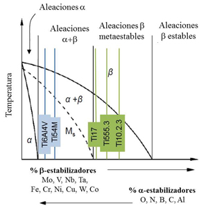
Figura 2: Diagrama de fases β-isomorhous indicando la posición de algunas aleaciones de titanio en función de su composición química.
Varios autores han analizado la dificultad en el mecanizado de la aleación Ti6Al4V, [12-20]. Armendia et al. [21] realizaron un estudio comparativo de maquinabilidad, en el que se concluyó una mejor maquinabilidad de la Ti54M. Comparando las máximas velocidades de corte que pueden emplearse de cara a alcanzar una duración de vida de herramienta, la velocidad al mecanizar Ti54M resultó un 10-15% mayor que al mecanizar Ti6Al4V. Debido a la similitud en propiedades mecánicas entre ambos materiales, la diferencia en maquinabilidad se atribuye a las diferencias en microestructura, y así los resultados obtenidos se entienden
Sin embargo, las publicaciones relacionadas con las aleaciones near β se centran más en aspectos del propio material (propiedades mecánicas, microestructura…) [8, 11, 22-24], pero apenas existen publicaciones que aborden estudios sobre la maquinabilidad de las near β de titanio. Arrazola et al. [25, 26] llevaron a cabo un estudio comparativo entre las aleaciones Ti555.3 y Ti-6Al-4V, en el que se observó una mejor maquinabilidad de la aleación α+β. C. Machai y D. Biermann [27,28] realizaron un análisis de maquinabilidad de la aleación Ti10.2.3 con diferentes microestructuras, en el que se observó la elevada influencia de las condiciones de corte y de la microestructura en el desgaste generado en el herramienta. Las diferentes microestructuras están ligadas a diferentes tratamientos térmicos, y condicionan las propiedades mecánicas del material, que son clave a la hora de determinar la vida de la herramienta.
En general las dificultades del mecanizado de aleaciones de titanio se asocian a:
- Las malas propiedades térmicas (baja conductividad térmica y el elevado calor específico) dificultan la evacuación del calor generado en el proceso de mecanizado, originando altas temperaturas en la zona de corte que aceleran el desgaste de la herramienta [7].
- Un área de contacto efectiva entre la viruta y la herramienta muy pequeña hace que las cargas termo mecánicas se concentren en la zona de la arista de corte, disminuyendo la duración de la herramienta [29]. El cráter generado en la superficie de desprendimiento se encuentra más cerca de la arista de corte, lo que debilita el filo y en consecuencia disminuye la vida de la herramienta.
- Un bajo módulo de elasticidad (110 GPa) da lugar a vibraciones perjudiciales para la pieza, pero sobre todo para la herramienta [6, 30].
- La elevada reactividad química a elevadas temperaturas con la mayoría de los materiales utilizados para fabricar las herramientas de corte [12-18], provoca el desgaste prematuro de las mismas por mecanismos de difusión entre otros [29, 31-34].
- Formación de la viruta segmentada [35-38], lo cual produce unas solicitaciones cíclicas, tanto térmicas como mecánicas, en la herramienta, provocando un deterioro más rápido de la misma.
Las herramientas de corte comerciales más utilizadas para mecanizar aleaciones de titanio son las plaquitas de metal duro sin recubrimiento [6-7, 29, 32-33], principalmente calidades K. Sin embargo, cada vez se emplean más las plaquitas de metal duro con recubrimientos (TiN, TiCN, TiN - TiC…), principalmente en fresado. Otra alternativa, cuyos resultados en desbaste son comparables a las herramientas de metal duro sin recubrir, son las herramientas de acero rápido sinterizado [43]. Además de aumentar la productividad de las herramientas de acero rápido convencionales, su coste es muy inferior a las de metal duro.
El CBN y el PCD presentan muy buenas prestaciones a la hora de mecanizar las aleaciones de titanio, alcanzando unas velocidades de corte de hasta 150 m•min-1 [14], y mejorando considerablemente la respuesta de las plaquitas de metal duro. Sin embargo, su aplicabilidad está limitada por su elevado precio [4-7, 15, 23].
Aleaciones de titanio estudiadas
Las aleaciones estudiadas han sido las siguientes: Ti6Al4V, Ti10.2.3, Ti17, Ti555.3 y Ti54M [10,26]. La composición química y propiedades mecánicas de las mismas están detalladas en la Tabla 1.
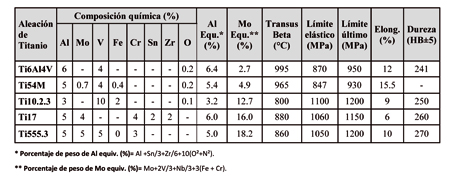
Tabla 1: Composición química en porcentajes de peso, valores equivalentes de Al y Mo y propiedades mecánicas de las aleaciones de titanio estudiadas.
El valor de aluminio equivalente indicado en la Tabla 1, es un indicador de la cantidad de elementos α-estabilizadores que contiene la aleación, y da una idea de la capacidad que cada aleación posee para obtener una dureza determinada. A su vez, el valor de molibdeno equivalente es un indicador de la cantidad de elementos β - estabilizadores en la aleación, por tanto, de la cantidad de fase β que va a retener el material a temperatura ambiente. Un mayor contenido de molibdeno equivalente se traduce en una mayor capacidad de obtener valores altos de resistencia límite a tracción. De esta manera, se puede decir que hay una relación directa entre las propiedades de cada aleación y su composición química.
La Figura 3 muestra las microestructuras de todas las aleaciones estudiadas. Se observa que presentan diferencias significativas en la cantidad y morfología de la fase primaria α, en la morfología de la fase β y en el tamaño de grano. En el caso de las aleaciones α+β se muestra una microestructura bi-modal, formada principalmente por granos equiáxicos de la fase primaria residual α y fases α y β alternadas en láminas formando una estructura Widmansttäten (Figura 3.a). Como puede apreciarse, además de tener un tamaño de grano más pequeño, la aleación Ti54M también tiene mayor cantidad de fase β que la Ti6Al4V (Figura 3.b), tal y como nos indica también el contenido de molibdeno equivalente.
Las aleaciones near β tienen una microestructura completamente diferente a la de las α+β, que consiste principalmente en precipitados de fase α dispersos en una matriz de fase β. La aleación Ti10.2.3 presenta un 50% de la fase primaria globular α (Figura 3.c), mientras que la aleación Ti17 se caracteriza por la fase α en las juntas de grano e importante tamaño de grano de la fase β, obteniendo una estructura Widmanstätten en la transformación de la fase β en α (Figura 3.d). Por último, la aleación Ti555.3 tiene un 20% de la fase residual globular α, junto con otra fase transformada de β en α obteniendo una estructura Widmanstätten (Figura 3.e).
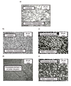
Figura 3: Microestructura de las diferentes aleaciones estudiadas. Las zonas claras se corresponden con la fase α mientras que las oscuras con la β. a) Ti6Al4V; b) Ti54M; c) Ti10.2.3; d) Ti17; e) Ti555.3.
Las aleaciones a estudiar poseen un amplio campo de aplicaciones, principalmente en el motor [2]. La aleación Ti10.2.3 posee una mayor resistencia a la corrosión que la Ti6Al4V, además de una buena combinación entre ductilidad y tenacidad, por lo que se usa fundamentalmente en el tren de aterrizaje, con el fin de absorber impactos de cierta magnitud y amortiguar el aterrizaje del avión [1,11,22] o en elementos de conexión entre alas y estructura. La aleación Ti17 presenta mejores propiedades mecánicas, como puede ser la vida a fatiga, por lo que su aplicación está orientada mayormente a los discos compresores y turbinas para motores. La aleación Ti555.3 muestra una excepcional combinación de tenacidad a la fractura e importante dureza y fácil obtención. Su principal aplicación es para elementos críticos como el tren de aterrizaje, compitiendo en muchos casos con la Ti10.2.3. La aleación Ti54M es una aleación de propiedades mecánicas semejantes a la Ti6Al4V, donde lo que se busca es un aumento de la maquinabilidad de la misma.
Ensayos realizados
De cara a poder entender con mayor detalle los fenómenos que acontecen en el proceso de mecanizado de aleaciones de titanio, el estudio de investigación se divide en dos grupos:
- Ensayos de vida de herramienta (3D): En condiciones cercanas a las industriales.
- Ensayos de corte ortogonal (2D): Con objeto de entender los fundamentos del proceso de corte.
En ambos casos, para realizar análisis de maquinabilidad rigurosos, el primer aspecto a considerar es el uso de una metodología bien definida. Para ello, se analizan los parámetros de entrada de los ensayos (avant-process), en este caso, (1) el estado de la máquina, (2) las herramientas que se pretenden emplear, midiendo los radios de las herramientas y las aristas de corte, (3) el lubrificante, (4) el material a estudiar, analizando la microestructura de la pieza y la dureza de la misma, y (5) se verifica que las condiciones de trabajo son las realmente establecidas (a través de parámetros del CNC).
Así mismo, se definen los parámetros de corte que se utilizarán en los ensayos, los cuales dependen de la pauta de ensayos que se ha planificado. En el transcurso de los mismos (in-process), se realizan mediciones de fuerzas de corte y potencia en ambos ensayos y mediciones de temperaturas en la cara de desprendimiento en los ensayos de corte ortogonal. Por último, se definen los parámetros de salida que se tendrán que analizar post-process que, en este caso, las plaquitas (medición de desgastes y análisis de deposiciones) y las virutas en los ensayos de vida de herramienta. La metodología seguida en los ensayos de vida de herramienta realizados se observa en las Figuras 4 y 5. A continuación se explican cada uno de los tipos de ensayo de forma más detallada.
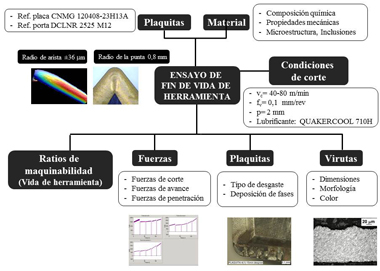
Figura 4: Diagrama fases de la metodología aplicada a los ensayos de vida de herramienta (3D)
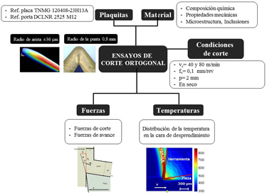
Figura 5: Diagrama fases de la metodología aplicada a los ensayos de corte ortogonal (2D)
- Ensayos de fin de vida de herramienta (3D)
Los ensayos de fin de vida se realizan en condiciones de mecanizado cercanas a la industria (ver Tabla 2), mediante un barrido de velocidades de corte para cada material, manteniendo constantes los valores de avance y profundidad de pasada. Consiste en realizar ensayos de 15 minutos de duración y medir el desgaste de la plaquita tras cada barrido.
La metodología de ejecución de los ensayos ha sido desarrollada siguiendo las directrices marcadas por la norma ISO 3685 [44]. Según el criterio para definir el fin de vida de la herramienta propone, la herramienta alcanza su fin de vida cuando se produce un desgaste de flanco uniforme (Vbmedia) de 0,3 mm, o un desgaste de flanco máximo (Vbmax) de 0,6 mm (Figura 6). Con este tipo de ensayo, se determina la velocidad con la cual la herramienta alcanza su fin de vida tras 15 minutos de mecanizado (Vcmax). A mayor Vcmax, mejor maquinabilidad.
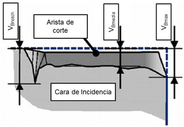
Figura 6: Criterio para definir diferentes cotas de desgaste en la cara de incidencia.
Para los se ha empleado el torno Danobat II CNC, con refrigerante Quakercool 710 H. Los ensayos se han realizado con las plaquitas CNMG 10408-23 H13A (grado K 15). Para el análisis del desgaste, se han empleado el Macroscopio Leica Z16 APO para medir el desgaste, y el Microscopio Electrónico de Barrido JEOL JSM-5600LV para detectar deposiciones e identificar los principales mecanismos de desgaste. Antes de cada ensayo se realiza un control de la arista de corte, utilizando el Perfilómetro Confocal Sensofar PLμ. Para la captación de fuerzas se ha utilizado el dinamómetro Kistler 9121 de tres componentes situado en el porta- herramientas, que mide las variaciones dinámicas en fuerzas de corte durante el mecanizado con un error de ±4%. El valor de las fuerzas se ha medido para un tiempo de mecanizado de 10 segundos, de manera que la presencia de desgaste no interfiera en el momento de la medición. Finalmente, se lleva a cabo un análisis de la viruta extraída de los ensayos, para estudiarlas en el microscopio óptico Leica Qwin. En la Figura 7 se muestra el set-up de ensayos, y en la Tabla 2 un resumen de los parámetros de entrada empleadas.
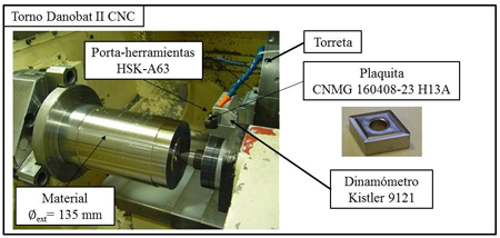
Figura 7: Set-up experimental para los ensayos de fin de vida de herramienta.
- Ensayos de corte ortogonal (2D)
El corte ortogonal se produce cuando el movimiento relativo entre pieza y herramienta es perpendicular (Figura 8). Los ensayos de corte ortogonal se han realizado en el centro de mecanizado vertical Lagun, sin utilizar ningún tipo de lubricante. Las plaquitas empleadas son TNMG 16 0408-23 H13A. Las probetas para corte ortogonal son tubos con un diámetro externo de 48 mm y espesor de pared de 2 mm. Se han hecho ensayos a dos velocidades diferentes (40 y 80 m/min) y con tres diferentes avances por vuelta (0,1, 0,15 y 0,25 mm), como se muestra en la Tabla 2. El set-up experimental se muestra en Figura 9.
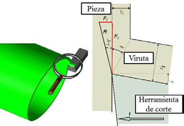
Figura 8: Ensayo de corte ortogonal.
Mediante el dinamómetro Kistler 9121, también empleado en los ensayos de fin de vida, se han medido las fuerzas de corte. Para cada uno de los ensayos se ha utilizado una arista de corte nueva, para que fenómenos de desgaste no interfieran en la medición de las fuerzas y temperaturas.
Para medir la temperatura en la cara de desprendimiento, se ha utilizado la cámara FLIR Titanium 550 M. Se ha medido el valor de la temperatura de 30 pixeles (resolución espacial de 10 μm) a lo largo de la cara de desprendimiento, calculando el valor medio de las mismas para representar la temperatura en la herramienta. Las mediciones tienen una incertidumbre de ±6% [45].
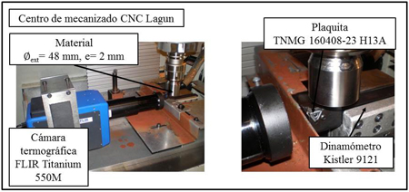
Figura 9: Set-up experimental para los ensayos de fin de vida de herramienta.
Debido a la limitación de material, los ensayos de corte ortogonal únicamente se han realizado en la aleación Ti6Al4V, por ser la aleación de referencia; en la Ti54M, para poder comparar los resultados entre las dos aleaciones α+β; y en la aleación Ti10.2.3, para realizar el estudio comparativo entre las aleaciones α+β y las near β. Se asume que los resultados obtenidos de la aleación Ti10.2.3 son cualitativamente extrapolables al resto de aleaciones near β.
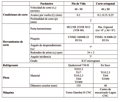
Tabla 2: Resumen da parámetros de entrada utilizados en los ensayos.
Resultados obtenidos
En esta sección se muestran los resultados obtenidos en ambos tipos de ensayo. Los resultados de los ensayos de vida de herramienta, que se explican en primer lugar, se pretenden entender y justificar con los resultados de los ensayos realizados en corte ortogonal, pudiéndose establecer correlaciones entre la maquinabilidad y estos parámetros, y dando más robustez a las conclusiones extraídas.
- Ensayos de fin de vida de herramienta (3D)
A continuación se muestran los resultados obtenidos en los ensayos de vida de herramienta de las diferentes aleaciones.
Vida de herramienta
En la Figura 10 se muestra el desgaste a 15 minutos de mecanizado (tiempo de vida de la herramienta según norma) para diferentes velocidades de corte y las diferentes aleaciones estudiadas. Se puede observar un máximo de velocidad de corte para cada aleación, el cual se puede definir por el repentino incremento en la curva de desgaste por un pequeño incremento de velocidad de corte.
De esta manera, se puede extraer la máxima velocidad de corte para estas aleaciones. Estos valores se aproximarían a 90, 80, 70, 60 y 45 m•min-1 para el Ti54M, Ti6Al4V, Ti10.2.3, Ti17 y Ti555.3 respectivamente, siendo la aleación Ti54M la de mejor maquinabilidad y la Ti555.3 la más difícil de mecanizar.
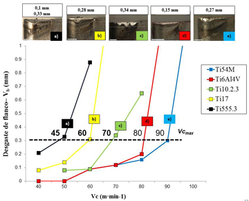
Figura 10: Desgaste en la cara de incidencia (Vbmáx) a 15 minutos de mecanizado (fv= 0.1 mm, p= 2 mm).
Fuerza especifica de corte (Kc), Fuerza específica de avance (Kf) y Fuerza específica de penetración (Ks)
Los resultados de fuerzas específicas de corte (Kc), de avance (Kf) y de penetración (Ks) se muestran en las Figuras 11.a, 11.b, y 11.c respectivamente. En las tres gráficas se puede observar que las aleaciones near β generan unos esfuerzos de corte superiores a los de las aleaciones α+β durante el mecanizado. Esto puede ser debido a unas mejores propiedades mecánicas de las aleaciones near β (Tabla 1). Esta tendencia se puede ver con mayor claridad en la gráfica de la fuerza específica de avance (Kf), donde la diferencia entre las fuerzas específicas de los tipos de aleaciones α+β y near β es mucho mayor.
Según estos resultados las mayores fuerzas de corte se generan al mecanizar la aleación Ti555.3 (2780 N/mm2, 60 m/min), mientras que los menores esfuerzos se han registrado durante el mecanizado de la aleación Ti54M (2248 N/mm2, 60 m/min), lo que supone una diferencia del 20%. La secuencia se repite en el caso de fuerzas específicas de avance, y además coincide con los resultados en fin de vida. Una tendencia semejante se observa en las fuerzas de penetración. Por tanto, puede decirse que existe una relación directa entre la maquinabilidad y las fuerzas específicas de corte generadas durante el mecanizado.
Se puede observar que los valores de la fuerza específica de corte (Kc) disminuyen a medida que aumenta la velocidad de corte. Esto se puede atribuir a una reducción del espesor de la viruta a medida que aumenta la velocidad con un avance constante.
Por otro lado, la fuerza especifica de avance (Kf) está directamente relacionada con los efectos de rozamiento a lo largo de la superficie de contacto y efectos del radio de la arista de corte, y por lo tanto, con la cantidad de calor generado en dicha zona [25]. Por consiguiente, es de esperar que en el caso de las aleaciones near β se genere más calor que en el caso de Ti6Al4V, especialmente en el caso de la aleación Ti555.3.
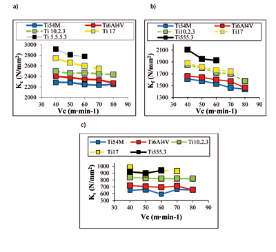
Figura 11: Fuerzas específicas obtenidas en los ensayos realizados: a) Fuerza especifica de corte (Kc); b) Fuerza específica de avance (Kf), c) Fuerza específica de penetración (Ks).
Análisis del tipo de desgaste
Tras el mecanizado se han analizado los dos tipos principales de desgastes en la herramienta (Figura 12) [41]: desgaste de flanco (en la cara de incidencia) y desgaste en la cara de desprendimiento. Aun así, a la hora de analizar el fin de vida, solo se ha tenido en cuenta el desgaste de flanco debido a que es el tipo de desgaste que mayormente predomina y que resulta más fácil de ser medido. Además de ello, es el efecto limitante de cara al mecanizado en la industria.
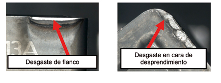
Figura 12: Modos de desgaste
En la Figura 13 se representa el desgaste en la cara de incidencia de las herramientas tras 15 minutos mecanizando.
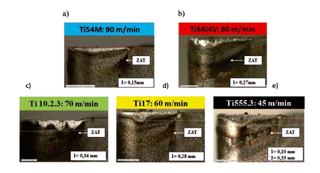
Figura 13: Desgaste de flanco tras haber mecanizado durante 15 minutos a sus respectivas Vcmax. a) Ti54M (Vc= 90 m/min); b) Ti6Al4V (Vc = 80 m/min); c) Ti10.2.3 (Vc = 70 m/min); d) Ti17 (Vc = 60 m/min); e) Ti555.3 (Vc = 45 m/min).
Como puede observarse, el desgaste se produce de manera uniforme a lo largo de la arista de corte, excepto en el caso de la aleación Ti10.2.3, en la que se observa un desgaste no tan homogéneo. Concretamente en la aleación Ti54M el desgaste uniforme es completamente uniforme. En todos los casos se observa que la superficie de la zona ha sido térmicamente afectada durante el proceso de corte. Esta zona también es menor en el caso de la aleación Ti54M. Además, en la 555.3 se observa una ligera depresión de la arista de corte.
El análisis de la superficie de contacto en la cara de desprendimiento de la herramienta confirma la presencia de material adherido en dicha zona al mecanizar cualquiera de las aleaciones, fenómeno que, hasta ahora, muchos investigadores habían observado al mecanizar la aleación Ti6Al-4V [29, 32]. Durante la operación de corte, este material adherido puede ser arrancado de la cara de desprendimiento, llevándose partículas de la propia herramienta. A este fenómeno, se une el de la difusión, propiciado por la reactividad química del titanio y las elevadas temperaturas alcanzadas. Esta eliminación de material da lugar a una craterización de la cara de desprendimiento [29] (Figura 14).
En la Figura 15 se muestra una imagen de la cara de desprendimiento de la aleación Ti6Al4V obtenida en el microscopio electrónico. Se observa que existe material adherido en la arista de corte. A pesar de la alta reactividad del titanio con los elementos que constituyen la propia herramienta de corte, no se observa formación de capa de carburo de titanio.
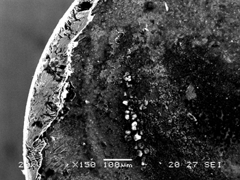
Figura 14: Deposición de material en la herramienta a) Ti6Al4V: Vc= 50 m.min-1, T= 15 min b) Ti10.2.3: Vc= 70 m.min-1, T= 15 min.
Análisis de la viruta
La viruta recogida después de cada ensayo se ha preparado metalográficamente (engaste, lijado, pulido y ataque químico) para analizarla mediante microscopía óptica. El objetivo de este análisis es observar la morfología de la viruta y su microestructura. Las imágenes obtenidas se muestran en la Figura 16.
Mientras que las aleaciones Ti6Al4V y Ti54M presentan una viruta segmentada con zonas de bandas adiabáticas a partir de velocidades de 90 m/min, las aleaciones Ti17 y Ti555.3 presentan virutas con estrechas bandas adiabáticas a partir de 40 m/min, incluso a velocidades más bajas. La frecuencia de formación de estas bandas adiabáticas es mucho más grande que en el caso de las α+β. Por ejemplo, a la velocidad de corte de 90 m/min en el Ti6Al4V las bandas adiabáticas presentan una frecuencia cercana a 30-40 kHz, mientras que en el Ti555.3 y Ti17 a 50 m/min se observan frecuencias cercanas a 50-80 kHz.
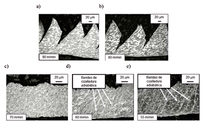
Figura 15: Microestructura de las virutas tras 15 min de mecanizado (fv= 0,1 mm, p= 2 mm): a) Ti6Al4V; b) Ti54M; c) Ti10.2.3; d) Ti17; e) Ti555.3.
Para una velocidad de 50 m/min, las aleaciones α+β presenta una viruta semisegmentada llamada ‘viruta transitoria’. Por otro lado, la aleación Ti10.2.3 presenta una viruta continua en todos los rangos de velocidad de corte analizados y la fase primaria α aparece más deformada a medida que aumenta la velocidad de corte. Para esta aleación, la corta vida de la herramienta está relacionada con el fenómeno de craterización comentado en el apartado ‘Análisis del desgaste’.
Las zonas de bandas adiabáticas son características en las aleaciones de titanio [14,39, 40]. La alta formación de dichas bandas explica el alto desgaste que sufre la herramienta. En condiciones de 'viruta transitoria' la creación de una capa de titanio, carburo, óxido de titanio, vanadio y otros elementos aleantes protege la superficie de la herramienta. En cambio, en condiciones de creación de las bandas adiabáticas, la herramienta es sometida a variaciones térmicas cíclicas y a cargas mecánicas que evitan la posibilidad de crear la capa de protección. La carencia de la capa protectora y las cargas cíclicas provocan una menor vida de la herramienta.
- Ensayos en corte ortogonal (2D)
Una vez realizado el estudio de fin de vida de las diferentes aleaciones, y haber establecido el ratio de maquinabilidad para las diferentes aleaciones, se muestran los resultados obtenidos en el estudio de mecanizado en corte ortogonal. El objetivo es medir fuerzas y temperaturas y verificar que existe una relación con los resultados obtenidos en los ensayos de fin de vida.
Fuerza especifica de corte (KC) y Fuerza específica de avance (KK)
En las Figuras 17.a y 17.b, se muestran las gráficas de fuerzas específicas mecanizando a 40 y 80 m/min respectivamente. Como puede observarse, estos valores disminuyen con el aumento de la velocidad de corte.
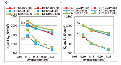
Figura 16: Fuerzas específicas de corte y de avance al mecanizar Ti6Al4V, Ti54M y Ti10.2.3 a) Vc= 40 m/min, fv= 0.1, p= 2 mm b) Vc= 80 m/min, fv= 0.1, p= 2 mm
A bajas velocidades de corte (40 m/min), las fuerzas específicas tanto de corte como de avance son mayores al mecanizar la aleación near β (Figura 17.a). Sin embargo, apenas existen diferencias entre las aleaciones α+β. Los valores más altos de fuerzas específicas de corte se han registrado con el avance de 0,1 mm, que es el más bajo. Estos valores son de 2.248 N/mm2 en el caso de la Ti10.2.3, 2.047 N/mm2 en la Ti6Al4V y 1998 N/mm2, habiendo una diferencia del 12% entre el máximo y el mínimo. La tendencia es la misma en las fuerzas específicas de avance: 1.769 N/mm2 en el caso de la Ti10.2.3, 1.455 N/mm2 en la Ti6Al4V y 1.426 N/mm2, con una diferencia del 20% entre los valores extremos. Tal y como se observó en los ensayos de fin de vida de herramienta, las fuerzas de rozamiento juegan un papel determinante en el desgaste de las herramientas.
A elevadas velocidades de corte (80 m/min), las diferencias tanto en fuerzas específicas de corte como de avance son mínimas, aunque las registradas para la aleación Ti10.2.3 siguen siendo ligeramente superiores β (Figura 17.b). Al igual que a bajas velocidades de corte, los valores máximos se dan con el avance más bajo: 2.040 N/mm2 en el caso de la Ti6Al4V, 2.028 N/mm2 en la Ti54M y 2.021 N/mm2 en la Ti10.2.3. En este caso, a pesar de que las aleaciones near α+β tienen mayores fuerzas específicas de corte que la near β, esta diferencia es del 1%, con lo que entra dentro de la incertidumbre del equipo de medición. Los valores máximos en fuerzas específicas de avance son 1.406 N/mm2 en la Ti6Al4V, 1.509 N/mm2 en la Ti54M y 1.469 N/mm2 en la Ti10.2.3.
La gráfica de temperaturas se muestra en la Figura 18. Como es de esperar la temperatura aumenta con las condiciones de corte, tanto con la velocidad de corte como con el avance. La aleación Ti10.2.3 alcanza siempre mayores temperaturas que las Ti54M y la Ti6Al4V. Las máximas temperaturas a 40 m/min son 864 °C (Ti10.2.3), 784 °C (Ti54M) y 715 °C (Ti6Al4V), habiendo una diferencia del 12%. A 80 m/min, esta diferencia se mantiene constante, y las temperaturas máximas son 1.057 °C (Ti10.2.3), 1.014 °C (Ti54M) y 946 °C (Ti6Al4V).
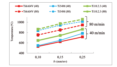
Figura 17: a) Temperaturas en la cara de desprendimiento a Vc= 40 y 80 m/min
- Resumen de resultados
En la Tabla 3 se puede observar una correlación del ratio de maquinabilidad con respecto al resto de parámetros medidos, para un ensayo de referencia. Para comparar las fuerzas específicas, en los ensayos en 3D se han tomado como condiciones de referencia Vc= 60 m/min, fv=0.1 mm y p= 2 mm, mientras que para los de corte ortogonal Vc= 40 m/min, fv=0.15 mm y p= 2.
Como se puede observar existe un grado de acuerdo, al menos cualitativo, entre el decremento de la maquinabilidad, y el incremento de las cargas termo-mecánicas a las que somete el material a la herramienta. Por ejemplo, en el caso de la aleación Ti-10V-2Fe-3Al hay un decremento de la maquinabilidad de un 12,5% debido, entre otras cuestiones, que se pueden relacionar directamente con el incremento de las fuerzas específicas de corte (+4%), de avance (+7%) y de penetración (+18%) en los ensayos de 3D. Así mismo, se observa que en los ensayos de corte ortogonal se observa que existe un aumento de las fuerzas específicas de corte (+6%), de avance (14%) y de la temperatura (14%).
Ello abre la posibilidad de que, a través de los ensayos de corte ortogonal (2D) de menor duración que los ensayos de 3D, se pueda anticipar al menos de manera cualitativa el grado de maquinabilidad de las aleaciones de titanio.
En el ámbito de fuerzas específicas se observa que existen diferencias entre los resultados en 2D y 3D, que es debida, además de a las condiciones de corte, principalmente, a la geometría de la herramienta.
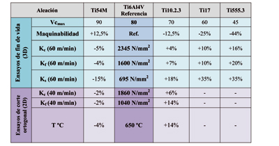
Tabla 3: Correlación del ratio de maquinabilidad con fuerzas de corte en fin de vida y fuerzas de corte y temperaturas en corte ortogonal.
Conclusiones
De este estudio de maquinabilidad se han extraído las siguientes conclusiones:
- Las aleaciones α+β tienen una maquinabilidad mayor que las near β, según el valor de Vcmax definido en los ensayos de vida de herramienta. En función de que aleaciones se comparen entré si, la maquinabilidad puede ser desde un 10 hasta un 50% mayor.
- El ratio de maquinabilidad de las aleaciones de titanio estudiadas decrece en el siguiente orden: Ti54M, Ti6Al4V, Ti10.2.3, Ti17 y Ti5.5.5.3, siendo sus respectivas Vcmax de 90, 80, 70, 60 y 45 m/min.
- En cuanto a la medición de fuerzas de corte, se observa buena correlación entre los resultados obtenidos en fin de vida y en corte ortogonal, ya que las tendencias son las mismas: Las fuerzas específicas de corte y de avance disminuyen con el aumento de la velocidad de corte. Esto puede ser debido a un ablandamiento local del material antes de ser mecanizado. Las fuerzas específicas también aumentan al disminuir el avance debido a un posible efecto de arista de corte.
- Tanto en ensayos de fin de vida como en corte ortogonal, se obtienen fuerzas de corte superiores al mecanizar las aleaciones near β. Esto se debe a unas propiedades mecánicas más elevadas. Las diferencias son más apreciables en Kk. Esto se traduce en una mayor sensibilidad a los efectos de fricción en la cara de desprendimiento al mecanizar las aleaciones near β.
- Existe una clara relación entre la temperatura y la maquinabilidad. Se alcanzan mayores temperaturas al mecanizar la aleación near β estudiada (alrededor de un 11% mayores). Debido a las bajas propiedades térmicas de las aleaciones de titanio, al aumentar las condiciones de corte el calor generado durante el mecanizado no puede ser disipado de forma efectiva, y se concentra muy cerca de la punta de la herramienta lo que da lugar a un desgaste prematuro de la herramienta.
- Para las condiciones de corte estudiadas, se observa la formación de viruta segmentada en las aleaciones Ti6Al4V y Ti54M, cuyas virutas son muy similares. Sin embargo, en las aleaciones de peor maquinabilidad (Ti17 y Ti555.3) aparecen bandas de cizalladura adiabática, que al parecer aceleran el desgaste de la herramienta.
- Existe una correlación, al menos cualitativa, entre el ratio de maquinabilidad, y las fuerzas específicas y la temperatura.
Referencias
[1] Lütjerin, G., Williams J.C., 2007, Titanium, Springer.
[2] Veiga, C., Davim, J., Loureiro, A., 2012, Properties and Applications of Titanium Alloys: A brief Review - A Review Advanced Materials Science, 32: 133-148.
[3] Boyer, R.-R., 1995, Titanium for Aerospace: rationale and applications, Advanced Performance Materials, 2:349-368.
[4] Rahman, M., Wong, Y.S., Zareena, A.R., 2003, Machinability of titanium alloys, JSME International Journal, Series C: Mechanical Systems, Machine Elements and Manufacturing, 2003, 46, 107 – 115.
[5] Bruhus Y., Sebring W., Noland D., 2007, Meeting the Challengue of Milling Aerospace Materials, Aerospace Manufacturing and design.
[6] Cui, C., Hu, B., Zhao, L., Liu, S., 2011, Titanium alloy production technology, market prospects and industry development, Materials & Design, 32: 1684 – 1691.
[7] Rahman Rashid, R., Sun, S., Wang, G., Dargusch, M. S., 2011, Machinability of a near beta titanium alloy, Proceedings of Institution of Mechanical Engineers, Part B: Journal of Engineering Manufacture, 000: 1-12.
[8] Rahman, M., Wang, Z.G., Wong, Y.S., 2006, A Review on High-Speed Machining of Titanium Alloys, JSME International Journal, 49: 11-20.
[9] Ezugwu, E., Wang, Z., 1997, Titanium alloys and their machinability – A review, Journal of Materials Processing Technology, 68, 262 – 274.
[10] Chen, W., Sun, Q., Xiao, L., Sun, J., 2011, Deformation-Induced Grain Refinement and Amorphization in Ti-10V-2Fe-3Al Alloy, Metallurgical and Materials Transactions A, 43: 316-326.
[11] Armendia, M., 2011, Machining of Titanium Alloys: A machinability Study of Ti6Al4V and Timetal54M alloys, Tesis Mondragon Unibertsitatea.
[12] Yang, X., Liu, R.-C., 1999, Machining titanium and its alloys; Machining Science and Technology, 3(1):107-139.
[13] Machado, A.-R., Wallbank, J., 1990, Machining of Titanium and Its alloys – A Review, Journal of Engineering Manufacture, 204: 53-60.
[14] Narutaki, N., Murakoshi, A., 1983, Study on Machining Titanium Alloys, Annals of CIRP, 32/1:65-69.
[15] W. Konig, 1979, Applied Research on the Machinability of Titanium and Its Alloys, Proceedings of the Forty-seventh Meeting of AGARD, AGARD, CP256, 1.1-1.10, AGARD Structural and Material Panel.
[16] S. Motonishi, S. Isoda, H. Itoh, Y. Tsumori, and Y. Terada, 1987, Study on Machining of Titanium and Its Alloys, Kobelto Technology Review, 2(1987)28-31.
[17] Calamaz, M., 2006, Feasibility of the dry machining process on the aeronautic titanium alloys, Fifth International conference on High speed Machining.
[18] Ribeiro, M., Moreira, M., Ferreira, J., 2003, Optimization of titanium alloy (6Al-4V) machining, Journal of Materials Processing Technology, 2003, 143-144, 458 – 463.
[19] Boyer, R.-R., 1992, New Titanium Applications on the Boeing 777 Airplane. Journal of Metals, May: 23-25.
[20] Fanning, J.-C., 2005, Properties of Timetal 555 (Ti-5.5Al-5Mo-5V-3Cr), J. Materials Engineering and performance. 14:788-791.
[21] Armendia, M., Garay, A., Iriarte, L.-M., Arrazola, P.-J., 2010, Comparison of the machinabilities of Ti6Al4V and Timetal54M using uncoated WC-Co tools, Journal of Materials Processing Technology, 210: 197-203.
[22] Aeby-Gautier, E., Settefrati, A., Bruneseaux, F., Appolaire, B., Denand, B., Dehmas, M., Geandier, G., Boulet, P., 2012, Isothermal alpha phase formation in beta metastable titanium alloys, Journal of Alloys and Compounds.
[23] Settefrati, A., Aeby-Gautier, E., Dehmas, M., Geandier, G., Appolaire, B., Audion, S., Delfosse, J., 2011, Precipitation in a near Beta Titanium Alloy on Ageing: Influence of Heating Rate and Chemical Composition of the Beta - Metastable Phase, Solid State Phenomena, 172-174: 760-765.
[24] Dehmas, M., Kovac, J., Appolaire, B., Aeby-Gautier, E., Denand, B., Da Costa Teixeira, J., 2011, β → α+β Phase Transformation in Ti17 Titanium Alloy: Chemical Composition and Crystallographic Aspect, Solid State Phenomena, 172-174: 396-401.
[25] Arrazola, P.J., Garay, A., Iriarte, L. M., Marya, S., Le Maître, F., 2007, Machinability of Near Beta Titanium Alloys Employed in Aeronautics, The 11th World Conference on Titanium (Japan), June 2007.
[26] Arrazola, P.J., Garay, A., Iriarte, L. M., Marya, S., Le Maître, F., 2007, Machinability of Titanium alloys (Ti6Al4V and Ti555.3), Journal of Materials Processing Technology (Pendiente de revisión).
[27] Machai, C., Biermann, D., 2011, Machining of b-titanium-alloy Ti-10V-2Fe-3Al under cryogenic conditions: Cooling with carbon dioxide snow, Journal of Materials Processing Technology, 211: 1175-1183.
[28] Machai, C., Abrahams, H., Biermann, D., 2012, Machinability of -titanium alloy Ti- 10V-2Fe-3Al with different microstructures, TMS Annual Meeting, 1: 919 – 926.
[29] Dearnley, P.A., Grearson, A. N, 1986, Evaluation of Principal Wear Mechanisms of Cemented Carbides and Ceramics Used for a Machining Titanium Alloy IMI 318, Materials Science and Technology, 2: 47-58.
[30] Yang, X., Richard Liu, C., 1999, Machining Titanium and its alloys, Machining Science and Technology, 3: 107-13.
[31] Hartung, P.-D., Kramer, B.-M., 1982, Tool wear in Titanium machining, Annals of CIRP, 32/1:75-80.
[32] Corduan, N., Himbert, T., Pulachon, G., Dessoly, M., Lambertin, M., Vigneau, J., Payoux, B., 2003, Wear Mechanisms of New Tool Materials for Ti-6Al-4V High Performance Machining, Annals of CIRP, 52/1:73-76.
[33] Farhad Nabhani, 2001, Wear mechanism of ultra-hard cutting tools materials, Journal of Materials processing Technology 115 (2001) 402-412.
[34] Jawaid, A.; Che-Haron, C., Abdullah, A. 1999, Tool wear characteristics in turning of titanium alloy Ti-6246 Journal of Materials Processing Technology, 1999, 92-93, 329 – 334.
[35] Bayoumi, A.E., Xie, J.Q., 1995, Some metallurgical aspects of chip formation in cutting Ti-6wt.%Al-4wt.%V alloy, “Materials Science & Engineering” A190 (1995) 173-180.
[36] Komanduri, R., 1982, Some Clarification on the Mechanics of Chip Formation When
Machining Titanium Alloys, Wear, 76(1982)15-34.
[37] Komanduri, R., von Turkovich, B.F., 1981, New observations on the mechanism of chip formation when machining titanium alloys, Wear, 1981, 69, 179-188.
[38] A. Gente, H.-W. Hoffmeister, 2001, Chip Formation in Machining Ti6Al4V at extremely High Cutting Speeds, Annals of the CIRP, 50/1, p. 49-52.
[39] Shahan, A., Taheri, A.K., 1993, Adiabatic shear bands in titanium and titanium alloys: a critical review, Materials & Design, 1993, 14, 243 – 250.
[40] Shaw, M., Vyas, A, 1993, Chip formation in the machining of hardened steel CIRP Annals, 1993, 42, 29 – 33.
[41] JC, L. & WA, B., 1972, Adiabatic instability in the orthogonal cutting of steel, 3, 477 – 81.
[42] Elmagrabi, N., Shuaeib, F., Haron, C., 2007, An overview on the cutting tool factors in machinability assessment, Journal of Achievements in Materials and Manufacturing Engineering, 23: 87-90.
[43] IMTS 2012, Chicago. www.imts.com/education/detail. Last visit 01/12/2012. [44] ISO 3685:1977, Tool-Life testing with single-point turning tools.
[45] Arriola, I., Whitenton, E., Heigel, J., Arrazola, P., 2011, Relationship between machinability index and in-process parameters during orthogonal cutting of steels, CIRP Annals-Manufacturing Technology, Elsevier, 60: 93-96.


