Visión 3D integrada en máquina-herramienta para la alineación de piezas en bruto
El mecanizado de piezas en bruto de grandes dimensiones requiere elevados tiempos de alineación previa en máquina. El proceso de alineación requiere de dos etapas: primero, caracterización de la geometría de la pieza en bruto y marcado de referencias de alineación, y segundo, su alineación en máquina. Este proceso requiere personal experimentado, y, además del elevado coste de personal y disponibilidad de máquina, existe el riesgo de no garantizar una distribución adecuada de sobrematerial disponible en todas las superficies a mecanizar, incurriendo en el rechazo final de pieza. El presente trabajo presenta una aproximación de visión 3D integrada en máquina-herramienta basada en tecnología fotogramétrica que permite incrementar el nivel de automatización y fiabilidad en los procesos de alineación, capaz de verificar y calcular de forma autónoma la alineación óptima de una pieza en bruto. El potencial de la nueva solución para reducir el tiempo total de alineación es demostrado en dos casos piloto de fresado.
Introducción
1.1. Alineación de la pieza en bruto: relevancia y problemática
Un problema importante a ser resuelto por un operario de máquina-herramienta es la colocación inicial de la pieza en bruto antes de proceder a su mecanizado. Las piezas en bruto son producidas por procesos de precisión relativamente baja, tales como la fundición y la soldadura, y muchas veces no suelen tener superficies fiables que faciliten el proceso inicial de posicionamiento.
El alineamiento inicial de la pieza en bruto respecto a los ejes de máquina (fresadora, torno, etc.) es un proceso crítico, ya que debe establecerse una colocación suficientemente precisa que garantice la existencia de sobrematerial en todas las superficies a mecanizar. Un posicionamiento impreciso puede provocar la existencia de un sobre-espesor excesivo en una superficie, y a su vez, en el lado opuesto de la pieza, la falta de material a ser arrancado, provocando el rechazo de la pieza final mecanizada. El coste de la pieza rechazada puede ser muy elevado, no sólo por el material de la pieza, sino también por el coste del proceso de fabricación realizado hasta ese momento.
Actualmente, la alineación inicial de piezas en bruto se realiza mediante procesos que requieren mucho tiempo, incluso del orden del propio tiempo de mecanizado para el caso de componentes de grandes dimensiones y valor añadido. Existen diferentes métodos de alineación, pero todos coinciden en su carácter eminentemente manual y no-repetitivo (diferente según cada geometría de pieza), incrementando la probabilidad de errores debido a factor humano.
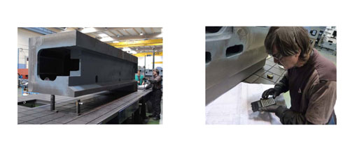
Como ejemplo característico, la medición de la geometría de la pieza en bruto puede realizarse mediante una Máquina de Medición por Coordenadas (MMC), pero en el caso de piezas de grandes dimensiones es más frecuente realizarlo colocando la pieza en una superficie plana (gramil) y utilizando herramientas manuales para la medición de alturas (figura 1). La caracterización de la pieza se realiza comparando patrones de diferentes alturas con las dimensiones de la pieza final (Figura 1, izquierda). Comparando las dimensiones medidas con la geometría de pieza diseñada a mecanizar (definida en planos, ficheros CAD, etc.), se marcan punto de referencia sobre la pieza (Figura 1, derecha) y se calcula su posición óptima en coordenadas máquina de forma que sirvan de fiduciales de referencia en la alineación de la pieza.
Tras el control geométrico de la pieza en bruto y el marcado de referencias sobre pieza, el posicionamiento de la pieza en máquina es el segundo y último paso antes de empezar el proceso de mecanizado. En este paso se miden las coordenadas máquina en la que se sitúan los puntos de referencia marcados en la pieza, ya sea con un palpador o con la propia herramienta de la máquina. De acuerdo a la desviación entre su posición real y su posición óptima deseada, se determinan las correcciones de alineación necesarias. El proceso es iterativo hasta comprobar un posicionamiento preciso en máquina de los marcadores de referencia, resultando en un proceso altamente ineficiente y con elevado coste de disponibilidad de máquina.
A la vista del coste y la dificultad que supone el proceso de alineación de una pieza en bruto, se identificó la oportunidad de desarrollar un nuevo método. El objetivo era desarrollar un sistema para caracterizar piezas de gran tamaño mediante herramientas de medición ‘portátiles’ (no MMCs), y al mismo tiempo, un sistema que facilitara la alineación final de pieza en la máquina herramienta. Otro de los objetivos definidos era que el proceso de alineación pudiera ser ejecutado por cualquier operario sin la necesidad de tener conocimientos acerca del proceso, avanzado hacia un proceso de alineación de máximo nivel de automatización y mínima dependencia a interpretación subjetiva sujeta a error humano. Con respecto a la precisión requerida en el proceso de alineación, es necesario empezar por considerar el sobrematerial medio de la pieza a ser mecanizada. Para piezas mecanosoldadas de gran tamaño se puede considerar un exceso de material de 5 mm en el diseño. En este caso, se debería de aceptar una precisión total de alienación de 1 mm. En las aplicaciones consideradas en este trabajo, con piezas provenientes de fundición hasta 5 m de longitud, el exceso de material considerado en el diseño puede fácilmente alcanzar los 20 mm. En ese caso, la precisión aceptable para el sistema de alineamiento rondaría entre 3 y 5 mm.
Actualmente ya existen métodos portables disponibles en el mercado para la caracterización de piezas en bruto. Entre las soluciones posibles están el escaneo estereométrico y el láser radar. Mediante ambos métodos se puede obtener una representación de la pieza en 3D con una precisión aceptable. Algunas de las limitaciones que presentan estas soluciones son debidas a la gran cantidad de información generada para la caracterización de componentes de grandes dimensiones. El procesamiento de la información de toda la pieza, y la necesidad de definir manualmente qué superficie medida tiene que ser comparada con las dimensiones de la pieza diseñada puede suponer un gran esfuerzo, fuera del alcance para un trabajador no cualificado. Teniendo en cuenta que para el posicionamiento de la pieza las superficies a tener en cuenta son sólo las superficies que se van a mecanizar, las soluciones mencionadas anteriormente suponen un sobre-esfuerzo y por tanto se rechazaron para el sistema desarrollado.
Para la medición de puntos específicos de pieza los métodos más relevantes son el láser tracker y la fotogrametría. En este caso se optó por la fotogrametría, debido a su bajo coste y simplicidad que presentaba. La precisión que se obtiene mediante las mediciones fotogramétricas está en el orden de 1/5.000 de 1/10.000 del tamaño de la pieza, suficiente para las especificaciones requeridas en el presente trabajo.
1.2. Estado del arte
Existen varios métodos automáticos para posicionar la pieza en bruto. Cuypers et al. presentan métodos alternativos al uso de MMC-s ‘virtuales’ para la medición de piezas de gran tamaño [1]. Uno de los casos prácticos que presenta es la medición de una caja de cambios previa a su alineación en máquina. En este caso, se utilizó un método de triangulación, el cual se comparó con un sistema de proyección de patrones (escaneado). El segundo método resultó ser mucho más costoso en cuanto a tiempo.
Para la alineación de los puntos obtenidos en la medición con el sistema de coordenadas de la pieza a mecanizar, generalmente se proponen aproximaciones donde se seleccionan puntos estratégicos como base para el ajuste. El resultado de la alineación se ofrece en representaciones del tipo CAD especificando el exceso o falta de material.
El alineamiento de superficies de geometría compleja debe ser realizado antes del mecanizado, al igual que el análisis metrológico de la pieza mecanizada. Se ha dedicado un gran esfuerzo a resolver esta problemática que es matemáticamente y computacionalmente complejo. Chatelain y Fortín abordaron el problema de distribuir el sobrematerial de la pieza, para así evitar el problema de falta de material. El artículo [2] describe el método matemático desarrollado, que consiste en emplear una nube de puntos en las superficies a mecanizar y el modelo sólido de la pieza mecanizada final. Se desarrolló un algoritmo de alineamiento nolineal que se debía de aplicar de modo iterativo, utilizando para ello el ya conocido algoritmo Simplex, el cual da lugar a una solución óptima sin derivar la función objetivo. Posteriormente, Chatelain mejoró el algoritmo mediante la utilización de una función logarítmica de penalización [3], dando lugar a una convergencia más rápida. Goch propone un algoritmo para el alineamiento de superficies complejas [4] mediante la minimización de Gauss (mínimos cuadrados) y de Tschebischeff (punto con mayor error). Goch desarrolló este método más allá, para poder utilizar una nube de puntos cada uno con su normal [5], en lugar de hacer uso de la definición matemática completa de la superficie. Benko et al. se concentraron en un problema parecido para encajar datos de varias curvas y superficies utilizando el método de ingeniería inversa [6]. Optimizaron el algoritmo de tal manera que se disminuyera el gran trabajo computacional que requería el tratar grandes cantidades de puntos. Galantucci et al. se centraron en el problema denominado ‘registration’ (el ajuste entre superficies de piezas medidas y diseñadas) realizándolo en dos pasos: bruto y fino [7], donde el ajuste bruto es realizado mediante la utilización de redes neuronales y el ajuste fino mediante algoritmos genéticos.
Hoy en día, el ajuste de una superficie escaneada con una superficie diseñada es bastante común en los sistemas comerciales de ingeniería inversa. Algunas soluciones disponibles en el mercado son las desarrolladas por Aicon, GOM, Konika Minolta, Delcam y Creaform. En cuanto a la precisión ofrecida por sistemas fotogramétricos, Rieke-Zapp et al. [8] demostraron que, una cuidadosa calibración de cámaras de alta calidad, puede dar lugar a una incertidumbre en el rango de 1/50.000.
Como conclusión, hay relativamente menor trabajo previo realizado en torno a la medición de la pieza en bruto, y sin embargo, bastantes aproximaciones propuestas sobre algoritmos de ajuste de superficies complejas, con disponibilidad de soluciones comerciales. No obstante, no se han encontrado contribuciones relevantes que traten sobre el alineamiento automático de la pieza en bruto.
2. Automatización del proceso de alineación
El objetivo del presente desarrollo es la obtención de un nuevo método automatizado para el alineamiento de piezas en bruto antes de proceder a su mecanizado. Un método automatizado debe de responder a los siguientes problemas:
- Caracterización (medición) de las superficies de la pieza a mecanizar.
- Obtención de la información requerida de la geometría de la pieza de modo automatizado, e independiente al sistema utilizado para su definición (CAD, etc.).
- Algoritmo automático de alineamiento ‘virtual’, calculando el encaje óptimo de pieza en bruto y geometría de pieza a obtener.
- Alineamiento en máquina.
El nuevo procedimiento desarrollado en el presente trabajo ha sido patentando (EP 11380068.4) y proporciona una solución integral con el siguiente enfoque:
- Caracterización de la pieza en bruto, mediante una solución fotogramétrica rápida y de bajo coste, basándose en la medición de los marcadores ópticos colocados solamente en las superficies a mecanizar (generalmente, superficies planas y cilindros),
- Determinación automática de la geometría ideal de la pieza, mediante la decodificación de las trayectorias de ejes de máquina disponibles en programas de mecanizado estándar (ISO en programa CNC o CAM),
- Módulo de alineamiento automático ‘virtual’, mediante el cual las coordenadas de los marcadores medidos y la geometría ideal de la pieza son automáticamente asociados y alineados, calculando la posición óptima en coordenadas máquina de marcadores ópticos de referencia (fiduciales).
- Sistema de visión 3D integrado en la máquina para medir la posición real en coordenadas máquina de los marcadores utilizados como fiduciales de referencia, calculando automáticamente la corrección requerida en la alineación de pieza.
Cada módulo se describe en detalle en los siguientes apartados. Los resultados son presentados y discutidos para dos casos piloto de fresado (componentes estructurales de una máquina herramienta, a los que se hace referencia como tipo A y B en las siguientes secciones), donde las piezas en bruto (provenientes de fundición) tienen que ser alineadas antes de su mecanizado con una precisión entre 3 y 5 mm.
2.1. Caracterización de la pieza en bruto
La solución adoptada consiste en emplear la fotogrametría con marcadores codificados y no-codificados sobre la pieza en bruto. La fotogrametría es una técnica utilizada para calcular las coordenadas 3D de un número de puntos de un objeto mediante un conjunto de imágenes tomadas desde diferentes posiciones y orientaciones libres. La figura 2 representa el proceso de fotogrametría. Se toman varias imágenes desde diferentes posiciones mediante una cámara. Mediante la identificación de los puntos codificados en diferentes imágenes es posible calcular la posición y orientación de la cámara en cada una de las imágenes, al igual que las coordenadas de los puntos codificados. A continuación se obtienen las correspondencias de todos los marcadores no-codificados en todas las fotos, con los que se realiza un cálculo más preciso de la posición de las cámaras y las coordenadas 3D de los marcadores, tanto codificados como no-codificados.
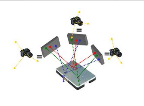
Los marcadores codificados se identifican mediante técnicas de visión artificial aplicadas a cada una de las fotos. Uno de los problemas más importantes que se da en la práctica al realizar medidas empleando esta técnica es la identificación de los marcadores codificados cuando su orientación respecto al eje principal de la cámara es superior a 45º. En este caso, los marcadores codificados no se pueden detectar de forma robusta. Este problema se solucionó utilizando una pieza poliédrica parecida a una semiesfera, donde se colocaron 14 marcadores (figura 3, arriba, izquierda). El ángulo entre marcadores adyacentes es menor que 25º con lo que se logra que al menos tres marcadores puedan ser siempre identificados desde cualquier punto de vista de la cámara.
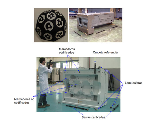
La figura 3 (abajo) muestra el proceso de medición de uno de los casos piloto (tipo B).
Los marcadores codificados se utilizan principalmente para calcular la posición de la cámara, mientras que los no-codificados son empleados para caracterizar las superficies de la pieza a mecanizar. Una de las importantes ventajas de utilizar la fotogrametría es que al emplear marcadores no-codificados sólo en las superficies a mecanizar, la identificación de las superficies que se deben de alinear puede realizarse de forma automática. Sin embargo una de las desventajas que presenta este método frente al escaneo completo es la necesidad de colocar los marcadores en los puntos característicos (más profundos, etc.) de las superficies a mecanizar, para garantizar el control de sobrematerial en todas ellas. No obstante, a efectos prácticos, no se consideró que presentase un mayor problema en los casos abordados. Para la caracterización de superficies cilíndricas también se emplearon marcadores no codificados con fijación magnética.
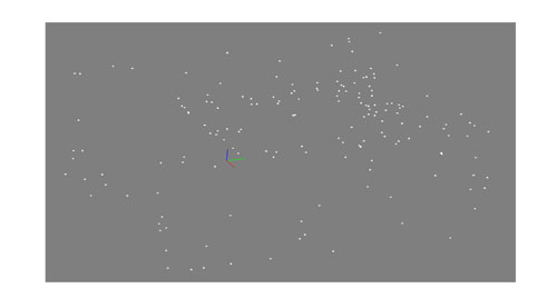
La figura 4 muestra el resultado de la caracterización de una pieza en bruto realizada mediante el método fotogramétrico (caso piloto de tipo B), facilitado por las coordenadas 3D de los marcadores no-codificados (>100 marcadores).
2.2. Decodificación automática de la geometría
En el estado del arte actual, el diseño o geometría final de pieza se define mediante archivos CAD de uso extendido. Para poder comparar la pieza medida con la geometría final, sería necesario extraer las superficies de interés del diseño desde CAD, con una fuerte dependencia con los diferentes estándares existentes en la estructura y formato de ficheros. Adicionalmente, el usuario necesitaría definir las superficies que deberán ser mecanizadas mediante un interfaz gráfico que se debería de desarrollar con este fin, dificultando la automatización de este paso del proceso.
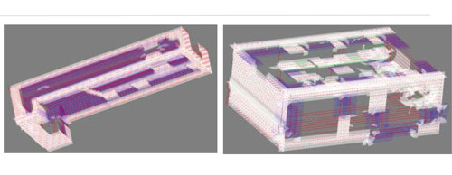
Debido a las desventajas que presenta el procedimiento que se basa en los archivos CAD, se optó por un procedimiento alternativo. El método desarrollado empieza por extraer la información geométrica de las trayectorias de acabado del código de CNC o CAM, ya que éstas contienen la información justa y necesaria para definir de forma precisa la geometría de las superficies a mecanizar. Además, una de las ventajas que presenta este método es que no requiere de un esfuerzo añadido para definir las superficies a mecanizar, ofreciendo el potencial de una automatización completa de este paso del proceso. La figura 5 muestra el resultado del método automático de decodificación para la obtención de la geometría de la pieza (superficies planas y cilindros) en ambos casos piloto (tipo A y B).
2.3. Algoritmo automático de alineación de la pieza en bruto
Una vez obtenida la información geométrica de la pieza, el siguiente paso consiste en alinear virtualmente la pieza en bruto con la pieza diseñada. Se ha implementado la solución con el método de mínimos cuadrados con restricciones, donde se minimiza la distancia de cada punto medido en la caracterización fotogramétrica (figura 4) a su correspondiente superficie asociada a la geometría final de pieza (figura 5) sujeto a la restricción de mantener un sobrematerial mínimo positivo en todas las superficies.
En este paso es necesario saber las correspondencias de cada marcador con la superficie en la que se encuentra. El método inicialmente relaciona el marcador con la superficie más cercana, con lo cual, en la mayoría de los casos, la relación definida será errónea. A continuación, se desplaza y alinea virtualmente la pieza en bruto de acuerdo al problema de mínimos cuadrados. Debido a este desplazamiento se obtiene una mejor alineación, y en cada iteración se recalculan las correspondencias entre marcadores y superficies. A medida que se avanza con el proceso de alineación, el número de correspondencias erróneas se reduce a cero y, una vez se hayan definido correctamente todas las correspondencias, el algoritmo converge muy rápidamente.
La figura 6 muestra esquemáticamente el proceso automático llevado a cabo para definir las correspondencias entre marcadores y superficies de la pieza. A la izquierda de la figura se representa la geometría final de pieza en negro, mientras que los puntos medidos y la pieza en bruto se han dibujado en azul y rojo. Los puntos y las flechas en azul representan las correspondencias efectuadas con éxito, mientras que las representadas en rojo significan que las correspondencias no son correctas. La figura de la izquierda muestra el resultado una vez efectuado la alineación, donde se puede observar que todos los puntos excepto el indicado en rojo se han asociado correctamente.

Una vez observado que se mantiene el número de asociaciones, y que los errores son bajos (en el rango de unos pocos milímetros, dependiendo de la aplicación), en las siguientes iteraciones se procede a aplicar las restricciones de sobrematerial positivo. Estas restricciones son muy sencillas: el exceso de material en cada uno de los marcadores debe de ser positivo y mayor que el valor que se haya especificado, por ejemplo, 1 mm. Una vez se cumplan estas restricciones, la solución es aceptable. Al contrario, si no hay solución que cumpla con las restricciones, la pieza en bruto no será válida para obtener la pieza final deseada. La gran ventaja de este método es que se sabe si la pieza es válida antes de proceder a su puesta en máquina, evitando los costes que conllevaría el mecanizado de una pieza que posteriormente sería rechazada.
En la figura 7 se pueden observar resultados de ajuste obtenidos en los dos casos piloto de fresado, como ejemplos característicos de predicción de falta de sobrematerial. Las superficies con suficiente sobrematerial se indican en verde, y las zonas indicadas en rojo significan que no hay suficiente sobrematerial en la zona. Para el caso piloto de tipo A (figura 7, izquierda), se han calculado sobrespesores mínimos y máximos de 23,77 y -1,66 mm respectivamente. Del mismo modo, para el caso piloto de tipo B (figura 7, derecha), se han calculado sobrespesores de 24,37 y -13,70 mm.
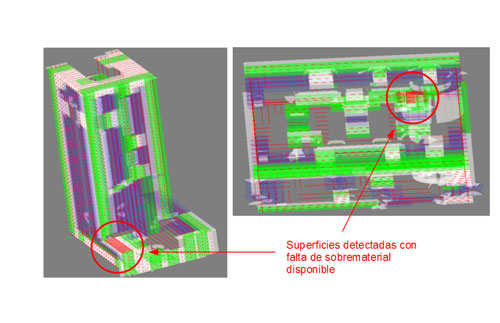
En caso de que la pieza no sea válida, se pueden adoptar diferentes soluciones para evitar el rechazo y así poder utilizar la pieza en bruto, según la funcionalidad que tenga la superficie donde existe la escasez de material y la pérdida de geometría que genera esa falta de material. Mediante la soldadura se puede aportar material localmente hasta unos pocos milímetros donde exista escasez de material. Para mayores faltas de material, el mecanizado de cajeras y posterior atornillado de bloques pre-mecanizados de material base permite la recuperación de faltas de sobrematerial de hasta varios centímetros. Para los ejemplos mostrados (figura 7), se podría aplicar el primer método de reparación para salvar el caso piloto A, mientras que el segundo podría ser utilizado para el caso piloto B. Las superficies que el sistema desarrollado considera son superficies planas y cilindros. Sería posible considerar más superficies, tales como las NURBS u otros modelos matemáticos utilizados para generar y representar curvas y superficies, como por ejemplo, moldes, matrices o álabes de las turbinas. Para este caso, se pueden encontrar varios métodos en la bibliografía (ver apartado 2.1). Sin embargo, tal y como se ha mencionado anteriormente, se considera más interesante hacer uso de la información contenida en los archivos de programa pieza que en los archivos CAD, con el fin de contar con un método universal y automatizable que sea independiente del sistema a utilizar para la definición de la geometría final de pieza.
2.4. Alineación en máquina
Tras obtener una alineación virtual que garantice suficiente sobrematerial en cada una de las superficies de la pieza a mecanizar, a través de un sistema de medida por visión 3D integrado en el cabezal de máquina se verifica la posición de la pieza en máquina midiendo las coordenadas máquina de marcadores ópticos de referencia dispuestos sobre la pieza en bruto. El sistema de medida consta de una cámara digital (5 Mpíxel, JAI BM-500) integrada en el cabezal de la máquina (figura 8, izquierda). La toma de imágenes de los marcadores de referencia, con un mínimo de dos imágenes por cada marcador (figura 8, derecha), permite determinar la posición 3D en coordenadas máquina de cada marcador. La medición de las coordenadas máquina de al menos tres marcadores de referencia permite determinar la localización y orientación relativa de la pieza en bruto. Como resultado, la diferencia entre la localización y orientación medida y la óptima calculada en el paso previo (ver apartado 2.3) permite calcular de forma automática las correcciones necesarias para una alineación precisa de la pieza.
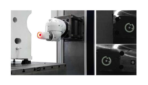
Los errores obtenidos al medir la posición de los marcadores fueron inferiores a 0,1 mm, más que suficiente para esta aplicación. Entre las principales ventajas del sistema integrado destacan, primero, la reducción del tiempo de medida, al sustituir procesos de medida por contacto por la medida por visión de marcadores de referencia ópticos, y segundo, la independencia respecto a la geometría de pieza para la definición de referencias fiduciales, al permitir el uso de marcadores de referencia ópticos dispuestos sobre cualquier zona fácilmente accesible seleccionada por el usuario.
3. Conclusiones
El objetivo del presente trabajo ha sido el desarrollo de un nuevo sistema de alineamiento de piezas en bruto de bajo coste, robusto, fiable y rápido, que tuviera una precisión total entre 3 y 5 mm para piezas hasta 5 m de longitud.
Debido al grado de automatización y universalidad de la solución, el uso del sistema no requiere personal especializado, ya que la principal parte eminentemente manual se limita a la colocación de los marcadores fotogramétricos para la caracterización de la geometría de la pieza en bruto y la posterior toma de imágenes (normalmente de 50 a 200). A partir de este punto, se procede al cálculo fotogramétrico y a la alineación virtual, siendo ambos procesos totalmente automáticos. Finalmente, el sistema estereofotogramétrico de visión 3D integrado en el CNC de máquina ayuda a guiar de forma rápida al proceso de alineación de pieza, sustituyendo a procesos lentos de posicionado basados en aproximaciones por contacto.
Las aptitudes que el usuario del sistema deberá de tener se resumen en lo siguiente: saber colocar los marcadores no-codificados en puntos que caractericen adecuadamente a las superficies concretas a mecanizar; colocar adecuadamente los marcadores codificados y tomar las imágenes necesarias para que el sistema fotogramétrico se resuelva de forma robusta; y llevar a cabo el proceso de alineación de pieza con la ayuda del sistema de visión 3D integrado en máquina. En conclusión, las habilidades que el usuario debe dominar son relativamente menores que en los procesos de alineación convencionales.
El procedimiento descrito en el presente trabajo es independiente del sistema usado para la definición de la geometría final de pieza (diseño CAD, etc.) dado que ésta se decodifica directamente desde las trayectorias de mecanizado disponibles en ficheros universales tipo CAM. La extracción automática y exclusiva de las superficies a mecanizar permite el cálculo desasistido de la alineación óptima de pieza a través de un módulo de alineación virtual.
Aunque en el presente trabajo se haya optado por la fotogrametría para la caracterización de la pieza en bruto, básicamente por su bajo coste y simplicidad, el láser tracker podría ser una alternativa muy fiable por su uso extendido. A costa de un precio más elevado y probablemente mayor tiempo de medición, se podrían obtener soluciones más precisas.
Referencias
[1] Cuypers, W., Van Gestel, N., Voet, A., Kruth, J.P., Mingneau, J., Bleys, P. Optical measurement techniques for mobile and large-scale dimensional metrology. Optics and Laser in Engineering, 2008, Vol 47, No.3-4, pp 292-300.
[2] Chatelain, J. F., Fortin, C. A balancing technique for optimal blank part machining. Precision Engineering, 2001, Vol 25, No 1, pp 13-23.
[3] Chatelain, J.F. A level-based optimization algorithm for complex part localization. Precision Engineering, 2004, Vol 29, No 2, pp 197-207.
[4] Goch, G. Efficient Multi-Purpose Algorithm for Approximation and Alignment Problems in Coordinate Measurement Techniques. Annals of the CIRP, 1990, Vol 39, No 1, pp 556-556.
[5] Goch, G., Tschudi, U. A universal algorithm for the alignment of any sculptured surface. Annals of the CIRP, 1992, Vol 41, No 1, pp 597-600.
[6] Benko, P., Kos, G., Várady, T., Andor, L., Martin, R. Constrained fitting in reverse engineering. Computer Aided Geometric Design, 2002, Vol 19, pp 173-205.


