This news article was originally written in Spanish. It has been automatically translated for your convenience. Reasonable efforts have been made to provide an accurate translation, however, no automated translation is perfect nor is it intended to replace a human translator. The original article in Spanish can be viewed at Calidad y definición de producto para el sector energético
Quality and definition of product for the energy sector
Dept. Metronic technician01/06/2005
The current changes in the industry of turbines have brought with them the need to make faster and at less cost. This has shown that traditional inspection methods have become obsolete by slow and inadequate at the time of the required results. With the growing complexity of the fan blades, simple inspection methods are not valid. To adapt to these changes, casting and forging companies are turning to automated digital inspection. Until recently the demand for precision in this type of inspection was a brake on the use of this technology. Now, with the introduction of the metering equipment ATOS II and ATOS III, we can get both, precision and automation.

Fig.1: Sections of a measured points cloud

Fig. 2: Points measured on the surface of a blade
Using the ATOS scanner and a rotating table motorized, smelting companies are able to measure up to 70 pieces in a day's work of 8. This non-conventional inspection includes the measurement of contours, small radios, base. The data are taken and processed through the use of macros in a few minutes per piece. The generated report includes colormap showing deviations on the CAD of the piece, positioning of pasa-no pass, cross sections of points, and the traditional XYZ of coordinate measurement machines. (figures 3 and 4).
For Assembly applications, the measurement of the full assembly area is critical to obtain the minimum distance between the faces of adjacent fan blades. This information is used to determine between blades, which, in turn, is used for the calculation of the volume of air to circulate in the turbine. This information is directly related to energy efficiency. (figures 5 and 6).

Fig.3: Deviation of the measurement to the nominal of the CAD

Fig. 4: Deviations in cross sections.
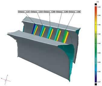

Fig. 5 and 6: demonstration of an automatic measurement to determine the minimum area of the throat.
The process
First of all, the blade to be measured is placed into a tool of measurement points of reference previously defined (Fig. 7). The next step is the execution of a macro, which defines the directory of the file, the name of the piece, the data to be processed and begins the process of scanning. The system automatically generates inspection reports which have been pre-defined for each component specific. Due to the need to measure different piece sizes on the same day, defined different sizes of useful mooring for each piece. In some cases, they can be built for the mooring of up to 4 pieces at the same time, this considerably accelerates the measurement. With this measurement of multiple parts, metrology departments are able to measure the blade altogether including specific points, contours, base.

Fig. 7: Useful for a single blade
Return on investment
Since the business of casting has begun to use scanners ATOS II & III, they have found a decrease in the time of inspection of each piece, to increase the performance of the departments of quality control. As an example, in the past, only a few points of control are inspected per piece. Now inspect the 85% of the full praise and 100% in the critical areas. With the possibility of a further inspection, the ATOS users are able to detect problem sen not expected areas, trends in the manufacturing and deterioration of the mold. With this information, manufacturers are able to optimize the mold change and in some cases cut the time of industrialization of a new piece in half.

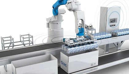
Fig. 8: Measurement automated by robot