Simulation of the process of flowforming applied to wheels
July 21, 2010
One of them is the process of flowforming, a powerful technology that allows you to lose weight non-critical areas of the tires in order to reduce weight. It should take into account the five wheels of the car to represent about 3% of the net weight of the vehicle, so they are pieces that should be optimized in terms of weight, considering also that influence directly in the management of the car and comfort when it comes to lead it. In addition, the rim accounts for 50% of the total weight of the wheel and only parts of the rim require large thickness, which is why the combination of the process of flowforming with of high strength steels can lead to a significant reduction of the weight of the wheels.
In the article are two different approaches to the problem of simulating processes of flowforming for wheels in high resistance steel. The first has been developed in Abaqus/Explicit and takes into account almost all the parameters of the process. The second is a simplified model, where only a small portion of the rim is simulated with Abaqus/Standard to check the different behaviour of the Interior and exterior areas of the rim.
The results of deformation are compared with experimental results, measured by an optical system. The comparison shows that there is a good agreement between them.
The process of flowforming
Flowforming process is carried out through the application of a uniform compression loading on the outer diameter of a component cylinder using a combination of axial and radial forces carried out by three or four rulinas controlled by CNC. During the process the rulinas rotate as the inner mandrel against which the tube is placed. According to the rulinas are moving along the axial direction, the material is compressed and deformed beyond its elastic limit and flows along the axial direction of the pipe [1].
")
The rulinas are decaladas axial and radially to balance the weight of the pipe and to minimize the forces of forming.
Model of finite elements
The typical method to optimize the processes of flowforming is trial and error, that it involves very long in the processes of implementation times to point. A way to get a better understanding of the process is to develop numerical simulation by finite element models. These models are also used as predictive tools to design and optimize flowforming processes.
Two different models have been developed to obtain results of deformations and to compare them with those obtained experimentally. The first model, called the real model, comes to represent the full experimental case taking into account almost all the parameters (geometry of the routines, speed of progress, gap between tire and mandrel..) The second, so-called model plane, is a simplified model that represents a small piece of RIM which is flat.
Case study
The selected tire flowforming process have the following characteristics:
- Length rim = 212 mm
- Internal diameter rim = 388 mm
- Initial thickness wheel = 2.6 mm
- Rotation speed = 800 rpm
- Speed of the rulinas = 550 mm/min
- Diameter rulina = 60 mm
- Distance between wheel and mandrel = 0.2 mm

The geometry of the rulina plays an important role in the process of flowforming. In this case, the three routines have the same geometry, which is a more important zone a part flat of 3 mm in length.

The rim is constructed with steel of high resistance HR60, also known as FB600. Tensión-deformación experimental data were adjusted to the Act of Hollomon
Σ = Kεn
(1)
with K = 884.87; n = 0.116

Real model
The first model was made with Abaqus/Explicit. The rulinas and the mandrel is modelizaron as rigid bodies (items R3D4) and the rim is modelizó with C3D8R elements.
During the process, the rulinas, as they move in the axial direction rotate also on its own axis due to the forces of friction that appear between the rim and the rulinas. Therefore the degree of freedom of the rulinas which corresponds to the rotation around its own axis does not have any preconditions to allow the already deformed rim material flow in the axial direction.

To validate the results of the simulation, some tires were marked on its surface with a mesh by electrodeposition, so major deformations through the optical system of analysis of deformations ASAME (Automated Strain Analysis and Measurement Environment) could be measured. Selected to be measured wheels have a reduction of thickness of 40%, meaning that his spends 2.6 to 1.56 mm thickness.

For results of deformation is not necessary to perform the full process simulation, because the deformations of the deformed material reach a stationary level in a given time. At that point, the simulation results show good agreement with those obtained experimentally.
Table 1: results of experimental deformation vs. numerical deformation results
| Maximum main deformation | Minimum main deformation | |
| Exp. | 52-55 % | 3-4 % |
| SIM. | 47-50 % | 1-2 % |
As explicit models calculation time depends directly on the minimum size of the smallest element [1], only had two elements in the thickness of the rim, so it is not possible to observe internal and external differences between the surfaces of the rim. To obtain this information, another model was developed.
Flat model
The flat model is a simplified model that only takes into account a small portion of the wheel... This portion has a size of 100 x 100 x 2.6 mm.
To avoid the problem of the time of calculation due to the size of the elements, Abaqus/Standard is used. In this case, there is no mandrel and routines are considered rigid elements R3D4, while the rim models with elements C3D8.
To take into account the presence of the mandrel, the nodes on the inner surface of the rim are constrained in their starting positions in the radial direction. Also, nodes in three of the four sides of the wheel are fixed. Only nodes of one side have the possibility to move to allow the material flow in the axial direction. In this model, only have simulated nine past the rulina on the wheel.

To make a proper comparison, the relationship between the directions of the real model and those of the flat model was established.
Table 2: relationship between the directions of the real model and those of the flat model
| Real model | Flat model |
| Axial direction | Address 1 |
| Radial direction | Address 2 |
| Circular address | Address 3 |
Six elements in the thickness of the rim were placed to see the differences between the internal and external surfaces of the rim. A case of reduction of 30% was simulated to assess these differences and compare the results of the flat model with those of the real model.
Table 3: comparison between the real model and the flat model for a case of reduction of 30%
| 30% reduction | Real model | Flat model | Flat model |
| Plastic deformation | - | Outer face | Inner side |
| Higher (higher level) | 32-35 % | 36-40 % | 30-32 % |
| Media (minor in map) | 1-2 % | 0, 5 - 1% | 0, 1-0, 2% |
| Minor (thickness) | 33-36 % | 37-39 % | 31-32 % |
| Equivalent plastic deformation | 120 - 130% | 135 - 150% | 78-82 % |
As you can see in table 3, deformation of the real model results are between you results obtained pair wings internal and external surfaces of the rim in the flat model, due to the lower definition which has the thickness in the real model. But the agreement between the two models, in terms of deformation is pretty good.
To better understand why the equivalent plastic deformation reaches as high values while deformations main have much lower values, you are represented the evolution of plastic deformation during the process in an element (9570) located in the outer surface of the rim and approximately in the center of the modelling portion of the rim.
")
As the event ran in an implicit code (Abaqus/Standard) time is not considered directly. Thus, in Figure 9, the values of the abscissa are not temporary values; they represent the number of steps in which the simulation is divided. Each pass of the rulina is divided into 3 steps of simulation; the first two are to place the rulina in his position and the third is the step in which the rulina deforms the rim, so that the deformation occurs between the points 2-3, 5-6, 8-9, 11-12, 14-15, 17-1820-21, 23-24 and 26-27 of Figure 9.
For the axial directions (address 1) and radial (address 2) there is a reversal of the sense of the values of deformation from strain values to values of compression in the axial component and vice versa for the radial component. The reason is the accumulation of material in front of the rulina before this happens about the same. As the material is compressed, the elements pass into a State of compression in the axial direction and a State of traction in the radial direction, because the volume of the element must be preserved and there is no distortion in the direction circular due to the restrictions of the model. (Figures 10 and 11).
 and after (bottom) of the 9570 element is distorted")
Once the rulina pass on the element, its state of deformation changes, because it reduces the thickness of the element, in such a way that the radial component goes into a State of compression, while the axial component deforms to reach a State of tension. (Figures 12 and 13).
 and after (bottom) of the 9570 element is distorted")
The value of equivalent plastic deformation is a value accumulated throughout the process:
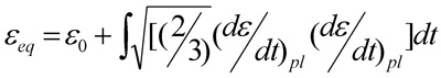
pl (dε/dt) to be the components of the tensor of velocities of deformation, so that the change in the sign in the radial and axial deformations has no influence in its final value. It depends on how is the path of deformation and not of the specific values of major deformations.
For the actual model, also ran the evolution of deformation during the process to an element located in the Centre of the wheel.
The behavior is quite similar to that expressed in the flat model. Axial deformations change its sign during the process as in the flat model and the same goes for the radial deformations, but for these there is an oscillation during the rest of the process that also affects the circular deformations. This could be a numerical effect due to the rotation of the material. For the equivalent plastic deformation, there is, as in the flat model a rapid increase in its value as the elements are deformed. After that, the value of equivalent plastic deformation tends to stabilize.
")
The two models show similar values and behaviors pair wings main plastic deformations and equivalent plastic deformation, so that both can be used to model the process of flowforming.
Conclusions
The process of high yield strength steels wheels flowforming can be an interesting process to reduce the weight of the vehicle. To understand how the parameters affect the results of deformation, we have developed two models of simulation. The first, so-called real model, developed with Abaqus/Explicit and represents the complete model taking into account almost all the parameters of the process. The second, so-called model plane, developed with Abaqus/Standard and represents only nine past the rulinas on a small portion of the rim.
On the one hand, the deformation of the first model results were compared with those obtained experimentally on a real tire with an optical measurement system. The comparison showed an excellent agreement between simulation results and the experimental. On the other hand, comparing the results of deformation of the two models each other, again showing a good deal. Therefore, the two models can be used to study the problem of deformation of tires through flowforming.
Future work
A better understanding of the process of flowforming and, in particular, the influence of the parameters in the mechanical and geometrical properties of the final piece, obtained by means of simulation is revealed as an essential element for the technical design of process. In fact, it is possible to reduce the time of design and making known the specifications of the product with regard to their structural strength. In addition the knowledge of the possibilities and restrictions of the technology of flowforming serves as support to the design of new products.
Thanks
This work has been developed within the framework of the draft ECSC "Influence of the parameters of the process of flowforming on behavior in fatigue of wheels of high yield strength for the automotive sector". The project has been implemented in cooperation with CSM (Italy), Magnetto Wheels (Italy), Arcelor-Automotive Application Research Center (France), LABEIN-Tecnalia (Spain) and Arcelor-IRSID (France). Funds provided by the European Community are especially welcome.
References
[1] Metals Handbook (Vol.14); PAG. (317). ASM (American Society for Metals) Editions, 1978.
[2] Abaqus Analysis User's Manual (version 6.6). ABAQUS Inc., 2006.