Interferometers laser in the diagnosis of machine tools
November 2, 2009
The laser interferometers are more precise measuring instruments in the industry. By this point they are used as reference measurement systems in the acceptance of machine tools. Thanks to its compact design, the new teams interferometric can be seen usually in laptops in the workshops of machining. These systems are now much easier to use and it reduces considerably the measurement time thanks to the help of the new software and new games of optics. New measuring options, particularly in regards to dynamic measurements, open up additional possibilities for diagnosis in machine tools. For example, the option of dynamic measurement enables the ability to record and analyse sequences of movements in units of speed. The speed and Acceleration can be also derived. Dynamic behavior of the axes can be can be evaluated using the analysis of Fourier Transforms. This allows laser interferometry to maintain its position of high-precision measurement equipment and be extremely effective in the future.

Currently, the machine tools are usually accepted and checked according to standard VDI/Unilog 3441, although new standards have been published as the ISO230. However due to the familiarity of the users and manufacturers of machine tools with the VDI standard, this is still very popular. With the support of new optical and software, the precision of a machine-tool according to VDI/Unilog 3441 positioning can be determined by drastically reducing the time required for the measurement. While in the past it could take several days make all measurements in a machine, currently the measurements they can be carried out in a matter of hours. The reduction of the time machine makes the measurements less expensive, allowing that to be repeated at more regular intervals, ensuring continuous monitoring of the accuracy. The smallness of the XL-80 (Figure 1) and great portability has allowed users of machines more often perform measurements in their workshops to receive the machines.

Determination of the position of a machine tool error
To set the error of positioned, the Laser Interferometer is aligned parallel to the axis to be tested as reference system (Figure 2). Wavelength of the laser is used to make the measurement. In the Interferometer, the laser beam is divided into a reference beam and a beam of measurement. Coherent wave fronts are superimposed to carry out the measurement. Measurements are based on a helium-neon laser. The index of refraction, which differs with respect to the measured in vacuum, should be compensated using the formula of Edlén, because otherwise significant measurement errors may occur. The table shows you exactly how influence factors of influence on accuracy without compensation of wavelength. It is clear that the coefficient of thermal expansion of the material influences the outcome of the measured values up to 10 times more than all the other parameters. The values of the table indicate that it is critical to compensate for thermal expansion of the material. It is clear how important is the precise determination of the environmental parameters for the accuracy of the system. To calibrate the pressure and temperature sensors, the new unit of compensation Renishaw XC-80, stores variations recorded in the sensor in a table of correction to get the maximum possible sensor precision.

The optics of alignment (Figure 3) facilitates the alignment of the beam. It allows deflect the beam laser on 35 mm per minute in the horizontal and vertical directions, with which to align the beam inclination is not necessary to do so in the laser head, aligning the beam only on the stretch of measurement between two mirrors. Therefore it is no longer necessary to have to move the lenses above and below the alignment of the beam. The head XL-80 of Renishaw laser is so small that it makes not necessary a tripod, because that can be positioned in the table of the machine using a magnetic base. This simplification of the measurement configuration allows to align the beam in less than a minute.

For the acceptance or verification of a machine, the axis to verify moves to various positions in a sequence defined depending on the selected test method. Laser interferometry system registers the current position and save possible variations. The result of this measurement is the graphic family of the VDI3441, which contains information in slack, dispersion and accuracy of positioning. As slack or variation of position errors are referred to as 'systematic errors' and to some extent can be compensated using certain parameters of the control. The random errors as the dispersion are caused by influences that can not be systematically removed.
The most common measurement methods are the 'linear' and 'Pendulum' (Figure 4). For the 'Linear' method, numerical control program is easy to create. However, the disadvantage is that some of the points are measured on a very large time interval and thermal influences can be mistakenly interpreted as dispersion. The advantage of the 'Pendulum' method is that multiple measurements are carried out in a continuous sequence in each position. Due to the increased work of CNC programming, this type of measurement has been less frequent in the past that the 'Linear' method. However, thanks to the option of automatic creation of programs CNC software of the laser, the method of the pendulum is becoming now more important. Once the change of position has been determined, the laser software can create the list of parameters required for correction of systematic errors of spindle passage. Depending on the type of control, sometimes compensation data can be transferred directly. The immediate subsequent measurement shows success in compensation.

New possibilities of evaluation of machines
The expansion of the system with the function of dynamic measurement interferometric opens up new possibilities in the evaluation of machine tools. For example, sequences of movements defined in forward speed can be recorded and analysed. The profiles associated with the speed and Acceleration allow us to obtain conclusions about the quality of the guides.
The behavior of vibration can be evaluated using Fourier analysis. The dynamic measurement involves measuring the laser with a high-frequency data, allowing in this way represent the sequence of movements of the optics of the laser. The measurement can be activated in different ways. The easiest option is to activate based on time. In this case, the data recorded by the Laser Interferometer are read on your PC at a constant frequency during a time interval. The maximum for the system frequency is several kHz, which cover the relevant range to determine the natural frequency of the machine tool. Activating external using the catchment of the machine system can establish a direct relationship between the axis of the machine and the Interferometer laser as a reference position sensor. This activation method allows a dynamic comparison ' reference / current ' between the system of recruitment and the laser measuring system but it does not consider the behavior of the numerical control (tracking error, step error compensation).

The measurement can be evaluated in graphs of forms of displacement/time, speed/time or acceleration/time. The development of the software can also do Fourier Transforms to create the frequency spectrum. This has resulted in new methods of measurement which are used for dynamic verification of machine tools.
- A conformity assessment required to move the axis to measure defined constant throughout its range of movement with a speed of displacement. The Laser Interferometer registers this movement and represents it graphically. The graphic speed/time uses the speed profile to highlight irregularities in the unit of speed. These variations can be caused by drags in the guides or spindle of traction or friction of protections.
- The test of positioned provides information about the behavior of approximation of the unit. A program of numerical control is used to complete a particular route between 2 positions. The Laser Interferometer represents this movement. Displacement/time graphic indicates as axis approximates the position goal, if that position is surpassed, for example the axis moves too far, he later retracts the objective position, or if it reaches the position without sobre-recorrido (Figure 5).
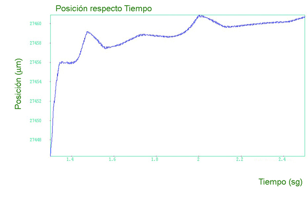
- A trial of response of steps shows how it responds to the 'input' axis a minimum displacement. The trial allows conclusions about the behavior of the control, effects of the static friction and positioning behavior. Use a program to move the axis (for example, 1 micron) increased at short intervals. The Laser Interferometer records this sequence of movements and represent them graphically. The curve of steps (Figure 6) shows if the defined positions are achieved mechanically.

A modular solution is the best
The varied applications of the Laser Interferometer result in a comprehensive profile of requirements. A modular concept has proven to be the best solution, since it can be adapted to the different needs of measurement, such as rotation and righteousness, relatively easy measurements. The trend in the increase of the laser to the measurement of route interferometers and new developments ensures that the laser interferometry will remain as the method selected in the future where the high resolution and accuracy are critical. Adaptation to new requirements profiles allows the laser interferometry settle firmly in entirely new applications.