Trials of characterization and validation of machine tools
Fundación Tekniker
01/09/2003
Introduction
There is abundant literature on testing of machine tools. Probably one of the oldest "modern" was written by Koenigsberger and j. Tlusty [1]. M. Weck [2] is the author of another classic book that considers several aspects of machines, including the test procedures.
A very comprehensive book on high speed machining was written by Arnone [6]. Among other things, it includes very interesting and practical proposals to measure different characteristics of the machines of high speed. The test proposed for the measurement of the processing capacity of blocks of the CNC was used by the authors of this article, producing significant results.
The parameters normally measured in machine tools are among many geometric accuracy, thermal deformations, static stiffness, dynamic behavior and scroll speed. Some precision of cutting tests are standardized in ISO 10791 and NAS 913. The ISO 230-4 standard also specifies tests for the verification of the accuracy in circular paths, but unfortunately, there are no trials currently standardized for the measurement of the accuracy of the trajectory of a machine.
The American ANSI/ASME B5.54 standard [4] takes into account many aspects of the CNC machining centers. Include environmental factors such as the thermal performance of the enclosure and the vibrations of the ground, as well as trials of machine. Among the trials of machine are considered static flexibility, repeatability, hysteresis, geometric precision and positioning, repeatability of subsets and the cutting capacity measures.
Many manufacturers of machine tools have defined its own tests for the characterization of the behavior of their machines. Of course, it is difficult to obtain information from them. On the other hand, in many cases, it is not easy to guess what particular parameter is characterized by the trial. For example, the authors are proof of an essay consisting of machining a straight trajectory of very small angle in a shaft. It is supposed to be characterized by testing the softness of displacement of the shaft that performs the short route, or in other words, the rigidity of the drive before the force of friction.
The static stiffness of a machine is a parameter that is measured by many manufacturers. Probably the most common method to measure is to apply a force controlled the tool or the head with the piece, and measuring the relative displacement. This test procedure is not very complicated and does not require expensive equipment, but still and all require some hours to do it. The measurement by means of a court trial might be more interesting to eliminate the influence of no linealidades and to better include the behavior of the drives.
An interesting essay used by some manufacturers and users of machine tools to characterize the static rigidity is to perform a milling tangential piece at constant speed until a point, stop for a few seconds, and continue the milling. The tool left a mark on the area of stop, whose depth depends on the static rigidity of the machine. The essay is somehow similar to the one proposed in the standard ANSI/ASME B5.54, and has the same problem: there is no way to move the result measured in microns to a value of rigidity.
The precision of contouring is becoming a very important parameter, especially in high-speed machines. The usual way of characterizing her is through the mechanization of parts pattern such as Mercedes, Cachan or NCG. Most of the time, outcomes are evaluated in a subjective manner although it is possible to measure the pieces obtained in a coordinate measurement machine. In practice, this measurement due to the long time required is not performed. On the other hand there is a clear guide to determine exactly what measure and how to get conclusions on the quality of the machine.
Several trials have been proposed [3] for the analysis of the behavior of the axes of advance in lathes, but they also require the verification of the piece machined out of the machine.
Another interesting proposal for the verification of machines by machining of parts pattern, which includes the justification of the interests of the different forms of the piece, was offered by e. Duc [5]. It can be argued that article proposed the evaluation of the majority of the results by visual analysis, while the remaining results are measured or calculated out of the machine tool. None of the proposed methods can be considered objective and simple at the same time.
This article proposes single trials comparable and fast for the characterization of the capacity of acceleration and jerk, the static rigidity and accuracy of interpolation. These trials are carried out without specific instrumentation and cover some of the aspects that are not correctly characterized by the standard tests.
Capacity of acceleration and Jerk
High speed machines using CNCs's high-performance, including the role of prior control (Feed Forward) as well as the Look Ahead. The previous control results in sudden changes in acceleration, which produces strong vibrations in the drive and the structure of the machine. To avoid this, the role of Look Ahead is used to limit the jerk (or acceleration ramp) to a level that the machine can handle.
It can be argued that the acceleration and the jerk are parameters in the CNC and that therefore there is no need to be measured. However, on occasions, it may happen that the machine is unable to reach the acceleration well programmed by limitations mechatronic or programmed value of excessively low jerk. Other times, the units in which these figures are scheduled may give rise to confusion. Experience shows that it is very interesting to measure these quantities.
For the measurement of the acceleration often used oscilloscope, or own oscilloscope of the CNC function, and represent the evolution of the speed making each axis to go from stationary to a higher speed. Dividing the increase in speed between the elapsed time to obtain the increase, it is estimated the acceleration of the axis. The problems of this procedure are that it must be run by an experienced person and that you can't make a good estimate of the capacity of jerk of the machine.
Measuring the real jerk is more complicated than measuring the acceleration and, in practice, not measured.
The proposed test to measure the capacity of acceleration and real jerk of each axis of the machine, is to measure the time required to perform two routes of different length and can be done with the help of a simple timer. The length of the routes must be selected in such a way that both reach the peak acceleration but not scheduled speed (which is the programmable maximum speed). Thus, the acceleration and speed versus time profiles have the form shown in Figure 1.

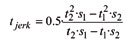
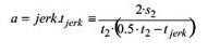
S1 is the length of the short and S2 of length. Similarly, if t1 is the time taken in the short andt2 the employee to make the long, it is estimated the time of jerk (time required to obtain the maximum acceleration) using the following expression:
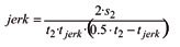
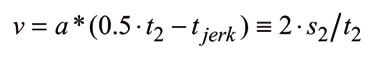
A second verification should be performed to make sure that speed programmed in the long journey has not been achieved. For this reason, the maximum speed reached in this journey is calculated by
As initial values of the routes can be selected 15 and 30 mm. If you need to change these tours it is advisable to keep them as separate as possible, being a practical limit s2> 1.25s1.
If not possible to obtain routes that meet the condition s2> 1.25s1, would indicate that the machine is not well balanced, i.e., that the value of jerk is too low for maximum speed and acceleration of the machine.
It is interesting to note that running these tests, have been found that many machines have sized engines to gain high accelerations in practice never obtained, because it reaches the maximum speed before reaching the maximum acceleration. An obvious solution is to increase the value of jerk, but then there are the structural limitations of the machine.
The acceleration is one of the parameters of the machine tools that can not be measured easily. This fact has resulted historically in that manufacturers have reported very exaggerated values of this parameter
To conclude, should take special care when they are designed large high speed machines. For example, a speed of work of 0.4 m/s and acceleration of 8 m/s2 requires a minimum value of jerk of 160 m/s3. To make a machine capable of supporting this jerk with a good dynamic behavior value, its natural frequencies should be above the 90Hz, which is far from the State of the art in large machines. Lower values of jerk are that the machine will never achieve this acceleration.
Following the proposed example, if the expected maximum jerk is 40 m/s3 , the maximum acceleration that can be obtained is 4 m/s2. Sized engines for larger acceleration would be wasting money, unless the rapid displacement (in vacuum) are an important part of the machining time.
Accuracy of interpolation
Currently many numerical controls are capable of circular path tests and compare the trajectory programmed with the background as measured by the rules, i.e., without the need for machining parts. These tests give good information, but without forgetting that paths with high accelerations, there may be differences notable between the extent of the rules and the position of the tool, because of the inertial deformations of the machine. As a reference, a machine of large dimensions, with a natural frequency of flexion of the RAM of around 37 Hz, will lead to inertial deformations of the order of 0.280 mm for an acceleration of 10 m/s2. A smaller machine, with a natural frequency of 60 Hz will lead to an inertial deformation of about 100 microns for the same acceleration. It is understandable that these large deformations will lead to the path of the tool is very different from the path detected by the system of measurement.
For the characterization of the machine in this case, is therefore most appropriate the increasingly widespread use of the ball-bar, or testing of milling (the aforementioned piece NAS 913 or ISO 10791 for example).
The information provided by the circular trajectories is far from being complete. These trajectories have acceleration changes very soft, and with the prior control function, the position as measured by the rules can be very similar to the commanded position. More complicated trajectories with sudden changes of speed and Acceleration, produce larger errors, which have to be reduced by the limitation of jerk of the function of Look Ahead.
There are several pieces of pattern which has been virtually standardised for the characterization of the behavior of high speed milling machines: Mercedes, Cachan, NCG, etc. The value of these pieces is proven by its wide acceptance. Its major shortcoming is the difficulty of obtaining objective comparisons. The measurement of the pieces must be conducted in coordinate measurement machines, which is a long process, and on the other hand, it is not defined what measure exactly and as process measures. In practice, these pieces are compared by visual inspection, which is prone to errors and impossible perform if the pieces are not available at the same time.
For objective and fast results, has developed a new piece pattern, shown in Figure 2. The piece can be verified on the same machine and the results are depicted in graphs which can be compared from machine to machine.

The first sections (arcs of circle) produce stairs of acceleration, i.e. jerk impulses. The triangular shape produces speed steps, smoothed by the radius of corners and similarly, the step produces a smoothing step of position.
The piece should be pre-mecanizada and then machining test should be done with a very low radial penetration: 0.4 mm is sufficient. The material of the piece is an easy-to-machined aluminum. The Court conditions are selected in such a way that shear forces are minimal and form errors may be due only to inertial forces and error tracking in the control loops. The diameter of the tool must be less than 20 mm, 12 mm to be a reasonable size. Figure 3 shows the machine, the tool and the machined piece.

The friction between the ball and the machined surface is a source of error because it produces a tangential deviation from the transducer. For this reason the penetration of the ball must be programmed to the minimum value to avoid the separation of the same during the measurement.
The programme of action must stop before any discontinuity in the trajectory. Thus, the minimum and maximum values of the transducer in the previous section are recorded.
It is also necessary to measure the time required in machining the workpiece. To this end, it is best repeated the journey in vacuum back and forth several times without stop, measure the total time and divide by the number of repetitions.
The test must be repeated for different rates of progress. The actual speed will be less that the programmed most of the time, due to the limitation caused by the role of look ahead and for this reason is proposed graphically represent the values of the maximum errors recorded in each of the sections against the time required to complete the path.
Experience has shown that in a high-performance machine, well adjusted, able to obtain excellent pieces "Mercedes", errors in the trial are of the order of 0.02 to 0.04 mm for machining of the order of 2.2 s. times worst performance machinesUnable to get good parts "Mercedes" have 10 times larger, 0.2 to 0.4 mm errors while machining.
Static stiffness

With the aim of obtaining a simple and fast court trial to determine static rigidity, it was considered necessary that the Court was made in a continuous trajectory so that it could be measured using a comparator in the head. To this end the procedure shown in Figure 5 was defined.

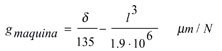
In these circumstances the force in the direction of progress is practically non-existent, the axial force is worth half of 25N and force perpendicular to the surface has a value half of 135 N. It is assumed that the influence of the axial force in the radial deformation is negligible.
The test can be done with the advance in directions X and and to measure the static rigidity in the directions and and X respectively. No trials to the axial direction is yet to be defined.
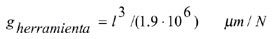
The measured deformation includes the deformation of the machine and tool. If a reasonably rigid piece is used, its deformation should be negligible. The deformation of the tool can be estimated using
In the tests carried out, the values of static stiffness following this proposal have a tendency to be about 10 per cent lower than for traditional measures.
References
[2] Weck, M., 1991, Werkzeugmaschinen Fertigungssysteme Band 4, Messtechnische Untersuchun und Beurteilung, VDI Verlag.
[6] M. Arnone, 1998, High Performance Machining, Hanser Gardner Publications, Cincinnati.
[4] ANSI/ASME B5.54, 1993, Method for Performance Evaluation of Computer Numerically Controlled Machining Centers, ASME, New York
[3] T. Bispink, 1992, Performance Analysis of Feed Drive system in diamond turning by machining specified test samples, Annals of the circumcision information resource center 41/1: 601-604
[5] E. Duc, C. Lartigue, d. Thiebaut, 1998, A test part for the machining of free-form surfaces, International Seminar on Improving Machine Tool Performance, circumcision information resource center, San Sebastián.