Sistemas de control y monitorización para la soldadura
Introducción
¿Y si un ordenador, como un soldador, pudiese captar una imagen de dónde se encuentra el arco eléctrico e inferir cuales son las características de soldadura adecuadas?
¿Y si un ingeniero pudiese detectar un problema con una célula de soldadura en una ciudad a través de su ordenador en otra?
Estas cuestiones ejemplifican áreas en las que se está trabajando en el desarrollo de la tecnología de soldadura. Un sistema de automatización de soldadura comprende un conjunto de componentes que tienen como función captar las características del proceso y compararlas con valores medios, predeterminados, ajustando estas características en tiempo real cuando sea necesario.
Una vez determinados los parámetros de la soldadura es necesario asegurar que se mantendrán dentro de limites aceptables durante todo el proceso. Para ello, se recurre al uso de sensores que leen los parámetros referidos, dependiendo del tipo de sensor, del tipo de parámetro a medir, del control y el ajuste de los parámetros realizado por los controladores incorporados en el sistema automatizado.
En cuanto a la manera de funcionar, los sensores pueden clasificarse en sensores que entran en contacto con la pieza, de forma mecánica o eléctrica, y sensores sin contacto, por ejemplo, los ópticos e inductivos.
Para la mayor parte de los procesos de soldadura, los parámetros monitorizados y comparados con valores de referencia son magnitudes eléctricas, como intensidad de corriente y tensión, temperatura, velocidad de soldadura, distancia entre la antorcha y la pieza, emisiones acústicas y luminosas, la fuerza aplicada en los electrodos y otros parámetros geométricos que caracterizan el proceso de soldadura. Otros fenómenos que ocurren durante la soldadura pueden ser monitorizados para controlar mejor la calidad de la soldadura, tales como las distorsiones del material provocadas por los ciclos térmicos y la estabilidad del keyhole en los procesos de alta densidad de energía. El ajuste de los parámetros monitorizados se lleva a cabo por los sistemas de control incorporados en la instalación. Estos sistemas pueden estar basados en algoritmos matemáticos que relacionan los parámetros del proceso con las características de los cordones obtenidos, en lógica difusa o en redes neuronales.
La dificultad principal en el control y monitorización en soldadura está en asegurar una respuesta en tiempo real de los equipos a un determinado desvío en relación a los parámetros óptimos de soldadura.
En los siguientes párrafos, después de una descripción de los principales tipos de sensores para monitorizar los procesos de soldadura de mayor difusión industrial, se encuentra de forma sistematizada la información existente relativa a sistemas de monitorización y control aplicados a la tecnología de la soldadura.
Tipos de sensores
- sensores para seguimiento de junta
- sensores para en control de la longitud del arco
- sensores para controlar la penetración de soldadura
Sensores para seguimiento de junta
En esta técnica es fundamental que el sistema capte y procese la información recibida relativa a valores de la junta a soldar y que consiga adaptarse a variaciones durante todo el proceso. Para el control de esta técnica pueden emplearse diversos sensores, entre los cuales se encuentran los sensores de contacto, sensores de ultrasonidos, sensores para monitorización de trayecto, sensores inductivos, sistemas de visión de luz estructurada y sistemas de guía por láser.
Los sensores de contacto guían al electrodo a través del contacto con las piezas a soldar. Los más simples son los sensores de muelles, guiados por ruedas. Los sensores de ultrasonidos determinan la distancia entre la pieza y la antorcha, a través de la medición del tiempo que tarda en emitirse y recibirse una onda de ultrasonidos después de reflejarse en la pieza, conocida la velocidad de propagación de la frecuencia ultrasonora en el medio de propagación. Una disposición de tres sensores de ultrasonidos permite localizar tridimensionalmente un punto en el espacio, siendo este su principio de funcionamiento en el control y monitorización en soldadura. Los sensores a través de arco eléctrico tienen la función de detectar variaciones de corriente y de tensión en el arco. En el seguimiento de junta, a medida que la antorcha avanza a lo largo del borde, esta puede sufrir desvíos en relación al borde. Estos desvíos están asociados a una variación de tensión de un pequeño arco eléctrico situado entre el sensor y el borde, siendo la posición de la antorcha corregida en función de la información recibida.
Los sensores inductivos evalúan la caída de un campo electromagnético provocada por la variación instantánea de corriente de soldadura. Estos sensores tienen la ventaja de no dejarse influir por la corrosión, tinta u humedad, y pueden emplearse para cualquier espesor de material. Como limitación de estos sensores, destaca el hecho de que deben conservarse a bajas temperaturas y no pueden ensuciarse con salpicaduras [1].
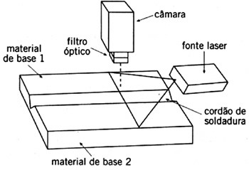
Los sistemas de visión de luz estructurada [2] utilizan una cámara CCD (iniciales en inglés de Charged Coupled Device, o dispositivo de transferencia de carga. Se trata de un semiconductor que transforma las señales de luz, p.e. imágenes en señales eléctricas) para capturar una imagen de esta luz, como se puede observar en la figura 1.
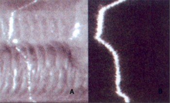
Para evitar interferencias con la luz emitida por el arco eléctrico se ha utilizado un filtro de paso de banda. Estos sistemas eran caros y tenían un tiempo lento de respuesta, pero la integración de sensores múltiples, mejores y más compactos, bajó los costes. Para piezas más gruesas donde es necesario emplear soldeo en varias pasadas, el sistema de seguimiento de la junta es el responsable de un correcto posicionamiento de la antorcha en la primera pasada, y en las siguientes, asegura que el cordón de soldadura está colocado en una posición correcta en relación a los cordones anteriores.
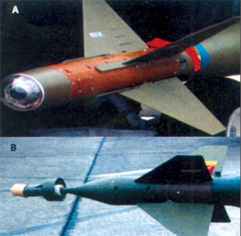
Los sistemas de guía por láser [3] fueron utilizados por primera vez por la industria de defensa y formaron parte del equipamiento militar que se conoce actualmente como "armas inteligentes". El principio básico de funcionamiento de estos sistemas es la captación por una cámara de un haz de láser inerte, reflejado por el blanco. El sensor capta la luz reflejada que incide en el blanco y guía al misil hacia éste con precisión. En la figura 2 se pueden observar algunos de estos sensores situados en el extremo del misil.
Sensores para el control de la longitud del arco
Es conveniente durante el proceso de soldadura que la longitud del arco no sufra variaciones [4, 5]. En los procesos más simples está operación se realiza a través del control de la tensión, en máquinas de soldadura de autorregulador para soldeo, ya que la tensión del arco indica claramente su longitud. En las máquinas de soldadura plana, el control de la longitud del arco debe hacerse mediante la intensidad de la corriente. Otra forma de controlar la longitud del arco es a través de sensores sonoros [6, 7], ya que la presión sonora aumenta a medida que aumenta la longitud del arco, en la gama de longitudes características de los arcos eléctricos en soldadura.
Los sensores fotoeléctricos están constituidos por un emisor infrarrojo y un receptor. Estos sensores poseen la ventaja de tener un bajo coste, ser robustos y no resultar afectados por la inestabilidad del arco.
Los sensores de luz y radiación espectral [8, 9] se basan en el hecho de que la intensidad de la luz total del arco aumenta de forma lineal en relación a la longitud de éste. Estos sensores tienen un coste elevado.
Sensores para el control de la penetración de la soldadura
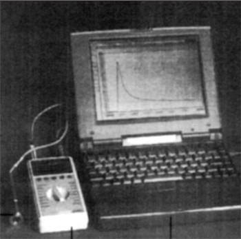
La penetración del cordón de soldadura es uno de los parámetros importantes a controlar ya que es un indicador de la calidad del cordón de soldadura e influye de forma determinante en el comportamiento mecánico de ésta. Para la penetración de la soldadura en la raíz, los parámetros de soldadura tienen una importancia crítica ya que es necesario asegurar la penetración total, rellenando totalmente la apertura de la raíz y la separación de la junta. Para hacerlo se puede emplear un sistema de control que emplee la radiación infrarroja como el que se presenta en la figura 3.
Los sensores infrarrojos se emplearon en los años 50 en la industria de defensa con la aparición de los misiles Sidewinder, que emplean un sensor de infrarrojos para captar la radiación térmica procedente del blanco. Estos primeros sensores tenían muy poco alcance y apenas podían emplearse en línea recta. Actualmente, estos sensores incorporan los más variado equipos y se utilizan en el control de la penetración de la soldadura como ilustra la figura 3.
Otro de los problemas reside en el hecho de que estos sistemas tienen un bajo ancho de banda, lo que implica que la imagen tarda algún tiempo en aparecer y desaparecer y esto provoca que una sombra de esta imagen aparezca algún tiempo en el visor una vez la imagen ha desaparecido. Desarrollos recientes de este tipo de cámaras conducen a aparatos extremadamente resistentes a la intensidad luminosa que pueden dar resultados similares a las cámaras infrarrojas [12].
Otro desarrollo reciente hace referencia a las posibilidades de uso de cámaras CMOS (CoMplementary Oxide Semi-conductor), ya que tienen un intervalo dinámico y una velocidad de adquisición de imágenes superiores a las cámaras CCD. Permiten también una mejor visualización del baño de fusión, que mejora la capacidad de evaluación de la calidad global del cordón durante su ejecución.
El control radiográfico se ha usado para verificar la calidad del cordón de soldadura. En esta técnica se coloca una fuente de rayos X encima de la pieza, mientras que la cámara y el intensificador de imagen se colocan por debajo de la pieza. Este sistema puede detectar un gran número de defectos de soldadura, como una fusión incompleta y porosidades, y ofrece una inmediata del interior de la soldadura. Se emplean sistemas controlados por ordenador para analizar la imagen y ofrecer las correcciones apropiadas. Este tipo de sistemas representan un gran costo y son complejos, por lo que aplicación es muy restringida hasta por asuntos asociados a la seguridad de la operación.
Sistemas ópticos de adquisición de imagen
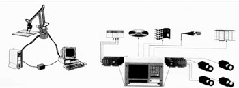
Es cierto que todos los objetos reflejan la luz que incide sobre ellos en mayor o en menor medida. La intensidad de la luz nos indica el color del objeto, siendo esta luz enfocada en sensores CCD (por ejemplo) a través de un sistema de lentes. Estos sensores convierten la luz visible en señales eléctricas. Los sensores CCD pueden ser de diversos tamaños, en función de la resolución necesaria para cada aplicación. Cuanto menor es el tamaño de estos sensores, y mayor su número, mayor es la resolución.
El tipo de cámara a utilizar en una aplicación dada depende del tipo de sensor que lleva incorporado para la conversión de imagen y de la resolución necesaria en cada caso. La fuente de iluminación es de extrema importancia pues no se consigue una buena imagen sin tener luz suficiente. La fuente de iluminación está condicionada, no sólo por el objeto a inspeccionar sino por su tamaño, color, forma, reflectancia y textura, entre otros aspectos.
El ordenador, equipado con un software y una base de datos apropiada, proporciona la llave para el control de la monitorización en soldadura, puesto que lleva incorporadas las placas de captación de imagen y las placas I/O.
Las placas de captación de imagen unen la cámara a un ordenador recibiendo la señal de vídeo de la cámara que va a ser digitalizada y convertida en una matriz de valores individuales (uno por píxel). Estos valores representan la intensidad de luz en cada punto, o píxel, de una imagen. En el caso de una cámara en color, se producen tres señales, una por cada color primario, siendo la placa de captación de imagen la responsable de digitalizar las tres señales simultáneamente, de lo que resultan tres valores por cada píxel. Los valores convertidos en matriz (después de ser digitalizados) serán comparados con el patrón de valores de la base de datos, y en función de las condiciones impuestas por la programación, una señal es introducida en las placas I/O que comunican con el PLC, de modo que, en conjunto, con el controlador del robot se puede controlar éste de modo eficiente y en tiempo real.
Otros sistemas ópticos de adquisición de imagen poseen un principio básico de funcionamiento análogo al descrito, presentando apenas algunas alteraciones en las características y tipos de componentes.
Técnicas de control automáticas
El seguimiento de junta [14] ya descrito anteriormente, es de extrema importancia en sistemas completamente automatizados, pues por muy bien mecanizadas que estén las piezas a soldar, siempre habrá algunas variaciones en su posicionamiento. A partir del inicio del proceso de soldadura los fenómenos de expansión y contracción térmica de las piezas debido a al ciclo térmico aplicado pueden causar deformaciones así como movimientos de las piezas frente a la antorcha, siendo estos problemas tanto más importantes cuanto más finas son las piezas a soldar.
El control de penetración de la soldadura es uno de los parámetros más importantes y más difíciles de controlar. Para este efecto se han desarrollado, entre otros, algunos sistemas que usan técnicas de ultrasonidos [15].
Respecto a la transferencia de metal, se ha observado que esta puede controlarse, en el proceso MIG/MAG, a través del análisis de las emisiones luminosas durante el desprendimiento de gotas de los hilos consumibles [16].
El calor transmitido a la pieza puede controlarse a través de la variación de la velocidad de avance de la antorcha, de modo que este calor sea desechado y que permita controlar el estado térmico del baño de fusión y del material circundante. Una imagen de los perfiles térmicos se obtiene a través de un sensor infrarrojo.
En lo que respecta al control de calidad [17], en aplicaciones críticas se emplean normalmente técnicas de control por ultrasonidos radiográficas para determinar si la soldadura no tiene defectos internos. Para aplicaciones menos exigentes, es suficiente el control superficial por líquidos penetrantes o una inspección visual del perfil del cordón de soldadura.
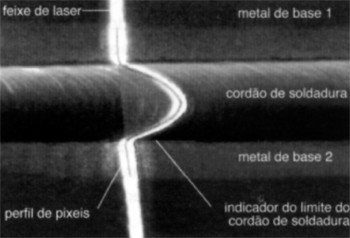
El sistema óptico presentado en la figura 5 puede emplearse para medir varios parámetros, como la altura del cordón, su refuerzo y la alineación de las piezas. Usando este sistema óptico con un proceso de imagen adecuado es posible obtener una respuesta en tiempo real.
Hardware y software para el control y la monitorización de la soldadura
Sistemas de hardware
Los ejemplos de mayor interés de sistemas de hardware [18,19] dedicados a la captación de información para soldadura incluyen el TWI QA Weldcheck, el TWI AMV Weldcheck, el Data Harvest Monarc y el OIS PAMS V.
Típicamente, estos sistemas comprenden una sola unidad de hardware unida a una equipo de soldadura que establece los parámetros de soldadura requeridos (corriente, tensión, velocidad de alimentación, etc.) y presenta la información recogida.
La ventaja principal para el empleo de estos sistemas de hardware es la eliminación del tiempo de desarrollo y sus costes, ya que es un sistema que, una vez comprado, está listo para usar. Estos sistemas son más robustos y propios para ambientes industriales. Pueden protegerse con facilidad de las elevadas frecuencias, lo que permite su uso en procesos de soldadura que tengan un procedimiento de cebado por alta frecuencia.
Su principal desventaja es su falta de flexibilidad, ya que fueron proyectados específicamente para grabar valores medios de los parámetros del proceso y no señales en forma de onda. De un modo general, cada sistema está proyectado para una aplicación específica, por lo que no se adaptan fácilmente a procesos alternativos, como por ejemplo, un muestreo de un gran número de parámetros simultáneamente, o incorporar un procesamiento de información extensivo o un control en feedback. Una vez escogido un sistema específico es difícil de modificar o mejorar y en caso de ser posible, acarrearía un gran coste. Como desventajas adicionales, está el coste inicial y los costes de manutención del sistema, ya que ambos serán más elevados que en un sistema de software.
Dos de los sistemas presentados están comercialmente disponibles en el mercado (QA Welcheck y el AMV Weldcheck). El primero es portátil, compacto y una máquina robusta para la monitorización de la corriente y la tensión eléctrica. La información relativa a la soldadura se presenta en una pantalla digital. Esta unidad proporciona protección contra las frecuencias y tensiones elevadas y es compatible con el software Weld Validator, empleado para el control de los parámetros en soldadura.
El AMV Weldcheck es un modelo portátil, compacto y una máquina robusta para la monitorización de corriente, tensión, velocidad de alimentación, velocidad transversal, temperatura y flujo de gas de la soldadura por arco eléctrico. La información relativa a la soldadura se presenta en una pantalla de cristal líquido. Esta unidad se autocalibra y proporciona protección de las tensiones y frecuencias elevadas y es también compatible con el software Weld Validator.
Sistemas de software
Los sistemas de software [20] integran los sistemas de hardware comercialmente disponibles en que las capacidades del sistema de software dependen de las capacidades del sistema de hardware escogido, así que dependen de la capacidad que tiene el software de aprovechar el potencial completo del hardware.
La ventaja principal de un sistema de software es su flexibilidad, ya que a medida que los parámetros en forma de onda puedan llegar a una tasa suficientemente elevada pueden ser grabadas y analizadas pequeñas fluctuaciones. Asumiendo que el hardware escogido es completamente programable por software, el software puede ser tan caro como necesario. Puede ser ajustado para iniciar el hardware, configurar los parámetros de entrada y controlar el proceso de captación. Otra de sus ventajas es la de poder utilizar el potencial del ordenador (procesador, disco...) para procesar extensivamente la información y utilizar la alta resolución del monitor para exponer la información en forma gráfica o en texto.
La flexibilidad del sistema depende de la facilidad con que éste puede ser mantenido y mejorado. La mayoría de las placas de captación son compatibles con numerosas aplicaciones de software, lo que permite que una misma placa pueda emplearse en diversas aplicaciones de software. De forma similar, la mayor parte del software disponible está proyectado de modo que una misma aplicación pueda emplearse con la mayor gama disponible de placas de hardware siguiendo criterios de implementación específicos.
La desventaja principal de estos sistemas es el tiempo y mano de obra necesarios en desarrollarlo. Una aplicación de software en si, necesitaría ser físicamente mantenida y perfeccionada de acuerdo con los nuevos sistemas operativos que van apareciendo. En función de la complejidad de aplicación y de su uso puede ser necesaria la producción de un manual de empleo (para minimizar el tiempo de manutención).
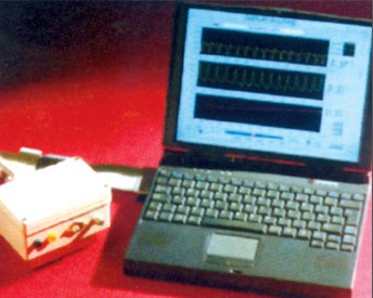
En lugar de desarrollar todo el software manualmente, puede emplearse un lenguaje de programación de cuarta generación, como el LabVIEW [21] o el HP VEE, con el fin de simplificar el diseño y los procedimientos de desarrollo. Empleando objetos visuales y diagramas de flujo, el programador puede desarrollar programas sin perder tiempo en escribir código de bajo nivel. La figura 8 muestra un sistema empleando LabVIEW.
Otra desventaja de los sistemas de software es que no son tan robustos como los sistemas de hardware, siendo por esto menos adecuados para ambientes industriales más severos.
Sistemas de control basados en lógica dispersa, algoritmos genéticos y redes neuronales
Los sistemas de control basados en lógica difusa se han empleado con éxito en un gran número de áreas. Estos sistemas están basados en reglas que incorporan variables de lingüística difusa para guiar el proceso de decisión. Pueden funcionar con reglas heurísticas, que muchas veces se presentan en sistemas complejos de soldadura. Recientemente, este tipo de sistemas se han adaptado con éxito a la soldadura. La señal se obtiene con una cámara que funciona como sensor y se procesa una imagen digital. La lógica difusa aprende con el proceso y adapta los parámetros a condiciones de soldadura diferentes, por sensorización del baño de fusión.
Los algoritmos genéticos [24] son algoritmos de búsqueda basados en el mecanismo de la genética natural, que tiene capacidad para encontrar rápidamente soluciones aproximadamente óptimas para sistemas complejos. Estos algoritmos presentan una mayor eficiencia asociados a sistemas de lógica difusa. Las redes neuronales [25] se emplean para el modelado digital [26] de procesos industriales. Estas redes fueron estudiadas recientemente para aplicaciones en soldadura y probaron que eran capaces de distinguir los modos de transferencia de metal y el control de los procesos de soldadura con una fiabilidad satisfactoria. Ya han sido presentados trabajos en que se emplean redes neuronales para el control de la longitud del arco eléctrico, para seguimiento de la junta y para el control de la penetración de la soldadura. Las redes neuronales son una herramienta importante de simulación por computador y de control de los sistemas industriales.
Conclusiones
Con los circuitos electrónicos modernos y los equipos sofisticados existentes es posible controlar operaciones en tiempo real con la calidad requerida.
El control de penetración de la soldadura es uno de los aspectos requeridos con más frecuencia por lo que prosigue el desarrollo de técnicas con esta finalidad.
Los sensores para captación de la imagen térmica y sensores láser son extremadamente eficientes, pero suponen un coste elevado. Los sensores ópticos son los más versátiles e inteligentes pero también son los más caros. Otros sistemas, empleados para el control de las características del arco, son eficientes en muchas aplicaciones y están disponibles a bajo precio.
En el mercado existen sistemas de hardware y software muy variados y adecuados para aplicaciones de monitorización y control de soldadura. La presente compilación de datos permite concluir que actualmente en el mercado hay una gran diversidad de productos para el control y la monitorización de la soldadura.
El usuario que busca una solución para un determinado caso deberá entender que un sistema eficaz para el control y monitorización de una aplicación determinada de tecnología de soldadura exige la integración, por ejemplo, de un determinado tipo de sensor con un equipo de soldadura y un sistema de posicionamiento y monitorización entre la antorcha y la pieza. Los conocimientos necesarios para la selección e integración de los diversos componentes de un sistema de este tipo no siempre son accesibles. Las empresas suelen optar por pedir consejo al proveedor de los equipos, que en muchos casos lleva a la implementación de las soluciones más adecuadas. No conviene olvidar que en casos de mayor complejidad o que requieren inversiones elevadas puede hacer necesario recurrir al consejo de instituciones con experiencia comprobada en este campo.
Una de las necesidades de los usuarios de estos sistemas es el desarrollo de procesos estándar de control de los diferentes equipos de monitorización disponibles en el mercado para que sea posible la integración de equipos de origen diverso y que tenga en cuenta razones de eficacia/precio. Se prevé que el uso de la lógica difusa, de las redes neuronales y algoritmos genéticos permita una evolución en este sentido.
Internet es una herramienta útil en el proceso de obtención de información técnica detallada y actualizada por parte de los propios fabricantes o distribuidores de sensores y equipos para la monitorización de las instituciones que poseen el conocimiento necesario en este campo. Una búsqueda puede ser iniciada con las siguientes palabras clave:
sensor + control + monitoring + welding robots + simulation software.
Bibliografía
- Cullison, A; Get that spatter under control, Welding J.; Abril 1999
- Lee, W.C. et al.; A study on the influence of reflected arc light on vision sensors for welding automation; Welding J.;
- Diciembre 1996 Low-cost laser tracking system; Welding & Joining - Product news; Mayo 1997
- Torch height control helps fabricator raise productivity, Welding J.; Marzo 1997
- Barborak, D.M.; Conrardy C.; Through-arc monitoring of weld quality during gas metal arc spot welding; 79º American Welding Anual Meeting; Abstracts. Abril 1998.
- Katsikas; Sokratis K.; et al; A genetic algorithm to for active noise control actuator positioning; Mechanical systems and signal processing; Vol. 9.
- Tang, K.S.; Application of the genetic algorithm to realtime active noise control; Real-time systems, Vol. 11, Nr. 3, 1996.
- Farson, Dave; et al.; Relationship of optical and acoustic emissions to laser weld penetration, Welding J.; April 1998.
- Dilthey, U.; et al.; Statistical process parameter surveillance in GMA welding; Int. J. for the Joinig of Materials Vol. 8 Nr. 3, 1996.
- Zhang, Y.M. and S.B.; Keyhole size stability in keyhole plasma arc welding ; 79º American Welding Annual Meeting; Abstracts; Abril 1998; Sesión 8; Process Control/Monitoring.
- Doumanidis, C.C.; Thermal modeling and adaptative control of scan welding; Welding J.; Noviembre 1998
- Biknell A.; Smith J.S. and Lucas J.; Infra-red sensors for top face monitoring of weld pools; Institute of Physics, Measurement, SCience and Technology, Vol. 5 N4, 1994.
- Norrish, J., Advanced welding processes; Institute of Physics Publishing, London, 1992.
- Zhang, S.P.; et al.; Noncontact ultrasonic seam tracking; 79º American Welding Annual Meeting; Abstracts; Abril 1998
- Aendenroomer, A.J.R; Den Ouden, G.; Weld pool osciliation as a tool for penetration sensing during GTA Welding; Welding J; Mayo 1998
- Kovacevic, R; Beardsley, H.E.; Controlling heat and metal transfer for droplet-based rapid prototyping, 79º American Welding Annual Meeting; Abstracts; Abril 1998
- Adolfsson, S, et al.; On-line quality monitoring in shortcircuit gas metal arc welding ; Welding J.; Febrero 1999.
- Tapp J., Mcllroy L.; Lucas W. Balfour C. y Smith J.S.; Realtime Low cost data adquisition systems for weld monitoryng; 8º International Conference on Computer Technology in Welding. Liverpool, 22-24 Junio 1998
- Data translation, DataAcq SDK User Man al; Primera edición UM- 15235-A, noviembre 1996
- Mokrov, O.A.; Dilthey, W.; et al; MAGSIM program software for analysis, optimization and diaagnostics of the process of consumable electrode welding with thin sheet joints in an active gas; Welding international; 1995.
- Travis J.; Wells L.K; LabVIEW for everyone, ISBN0-13-268194-3, Prentice-Hall Inc., 1996
- Kobayashi, M et al, Development of full automatic welding systems for TIG all positions, IIW DOC XII, 1460-96
- Fromm P., Drews P.; Advanced sensor-robot communications, IIW DOC XIII, 1405-95
- Oshima, K. et al, Applications of genetic Algorithm and fuzzy control to seam tracking, IIW DOC XII, 1401-95
- Oshima, K. et al, Controlling of torch altitude and seam tracking by using neural network in short circuiting arc welding, IIW DOC XII, 1473-96
- Chen, S.B. et al, Intelligent methodology for sensing modelling and control of pulsed GTAW, welding journal, junio 2000.

