This news article was originally written in Spanish. It has been automatically translated for your convenience. Reasonable efforts have been made to provide an accurate translation, however, no automated translation is perfect nor is it intended to replace a human translator. The original article in Spanish can be viewed at
Alineación acertadaFundamental requirement for the geometric inspection of industrial parts
Right alignment
Traian Onaciu
(director ASCAMM Foundation Metrology Department)15/05/2003
The current of the majority of parts industrial design is done with the help of three-dimensional modeling CAD systems. The result of a geometric modeling of piece is a computer file. From this the planes with the explicit definition of the piece are made including, views, cuts, details, caption elements, geometric and dimensional tolerances, surface etc. finishing specifications The assessment of the actual size of the geometric specifications of definition is essential for the certification of manufacturing processes. Then intends to produce an approach to the problems of the measurement process, precisely to the phase of alignment of pieces, because of the importance this in confidence results
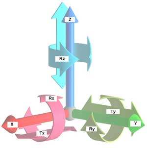
Geometric analysis of complex pieces is done with the help of three-dimensional measuring machines. To start this process it is necessary to fix the representative sample in the working environment of the machine. It will thus get the blocking of all and each of the six degrees of freedom which has the piece in the space.
Figure 1 degrees of freedom
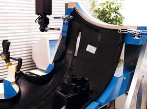
Figure 2 piece in inspection on fixing tool
For final parts to produce thousands of units are normally a useful for verification. This is a mechanical device that ensures rigidity, accessibility and repeatability. This means that parts of little thickness will win the necessary consistency for exploration by discreet contact; the shape and orientation of the tool allow access of a single Stockade to all areas of interest and during the process of "puts / removes" there is no any geometric error of the piece. On these useful defined and are marked benchmarks that help to create the required coordinate system for the inspection.
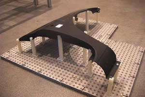
Figure 3. Useful for setting RAPID FIT
These materials tend to be expensive and for parts in phases of development or small series are not available.
Fixtures of fixation of low cost that are achieved in the short term are preferable for these cases. In the Metrology Department of the ASCAMM Foundation we propose RAPID FIT solution. This system offers the possibility of building columns support and fixation, that connect the piece with a base of fixation of modular design. In these columns, the areas of support for the piece is achieved by techniques of rapad prototiping, using the CAD model of this. An example can be seen in Figure 3.
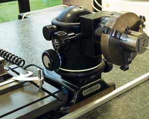
Figure 4. Useful of modular fixation on AIRBASE
We also have a set of useful of fixation of modular structure whose composition are: foundations of fixation on cushion of air, spherical joints with three perpendicular turns, calipers, etc. platforms which offers the possibility of constructing bindings with very good repeatability and accessibility. A composition of these modular elements can be seen in Figure 4.
Methods for aligning
There are standards such as ISO 1101 - or ASME and 14.5M-1994 recommending that as the industrial pieces must align 1983. Rules assigned to the designer of the piece the responsibility of defining the system of reference, through representative characteristics and restrictions on these. Such information will be reflected in the levels, through a symbolism, whose reading and interpreting allow the metrólogo to reproduce the reasoning of the designer.
Is it possible to align by only three points? Find the answer to this question has been a major challenge for geometric measurement software developers
Figure 5. Graphical definition of benchmarks
Method 3_2_1
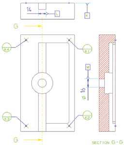
This method implies the most representative feature to block 3 of the degrees of freedom. The most common is use for this purpose a plane. It then explores a line, situated or projected onto the previous level, which can block other 2 degrees of freedom. It should be noted that failure to comply with the requirements of form (for cutting, righteousness) disqualifies characteristics in care for use in alignment. Finally just need one point to block the last degree of freedom of the coordinate system. If any of the features involved in alignment fails to meet requirements of form it is necessary, prior to follow, check the beneficiary of the piece to find an alternative solution. Also it can involve alignment processes other geometric primitives as: cylinders, cones, slots, Bulls or parabolic surfaces. The most committed feature we call, datum primarium it. This defines the first axis of the reference system. The second axis defines it the feature that we call datum secundarium. The third axis is implicit, being perpendicular to the plane defined by the previous two axes. The origin of the coordinate system defines it the feature that we call terciarium datum. Reference elements are marked with the letters K, L, M in Figure 5.
The alphabetical order of the letters that identifies the elements of reference corresponds to the order of importance of these in the definition of the system of coordinates, where is the letter more high which corresponds to the primarium datum.
"best FIT" method
In this process of measuring software calculates the transformation matrix is to relate a few representative points, measured on the piece with their respective theoretical coordinates.
After the first transformation is iterations in which they become to measure the same points in the new coordinate system to achieve a more accurate alignment, seeking to minimize the deviations of the points. We note that this method does not always converge towards improved results. In addition none of the points is fully placed. The repeatability of the method is low. However it is used for the evaluation of the quality of the free surfaces in which the points of final anchors are not determined.
T1 table restrictions RPS
Method A_B_C
Is it possible to align by only three points? Find the answer to this question has been a major challenge for geometric measurement software developers. Some of these there is implemented a function which fulfills this need. Car manufacturers require that in the process of alignment to ensure the blockade of the degrees of freedom of individual pieces or sets of similar to the editing process that is performed with the help of the industrial robots. These requirements are shown in tables RPS that mark the tolerance of admissible positioning for the representative points involved in the Assembly.
Those coordinates that have value "0" for the tolerance of position necessarily mark the nominal value, while the others could oscillate within the assigned area of tolerance. Table T1 presents an example of RPS restrictions for the points A, B and C. name It can highlight a similarity with the previous method 3, 2, 1. The three points crashes the x coordinate. This means getting the first axis like X direction. The points A and B, have to fulfil the coordinates in and they are going to define the second axis as Z, perpendicular to the previous direction. Point A, the more committed will define the origin of the coordinate system by means of basic dimensions. It should be noted that the points that are involved in this process of alignment must be centres of primitive geometric confidence as: spheres, colisos, slots, cubes etc.
In dimensional metrology laboratory of the ASCAMM Foundation has developed a program capable of responding to this problem. It is of a module for calculation in Microsoft Excel ".xls" format that allows a continuous interaction with the user. To begin with they have to fill areas of nominal and actual coordinates of the points A, B, C. For each are marked restrictions and freedoms, according to the RPS table. Symbol "0" are marked in table T2 obligations and with "1" freedoms.
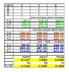
T2 table of calculation of transformations
In the same Excel book, next to the main road, there are 21 leaves rather than calculated all the versions that you can imagine from the data and the restrictions on entry. The system indicates the impossible solutions, particular situations (points colineares, widely dispersed points etc.) and where appropriate recommends changes in the table of restrictions, to minimize the errors of position of the points B and C. They have freedoms one and respectively in two axes, while the point A, which is the narrower, always meets the three coordinates. In the end the program offers the magnitude of the three transfers and the three turns to overlap the actual points with the nominal in the desired frame of reference. A comparison between the nominal distances and actual distances, found among the surveyed points is also. If a piece of plastic that all these distances are shorter or longer than expected, we are in the case of an error due to the use of a material with inappropriate contraction coefficient. If there are two of these distances are smaller and the third is larger than expected, we are in the case of a twisted piece. To not rely on any software of measurement, this program can offer a quick solution to problems of alignment in metrology, to problems of overlap of points scanned on surfaces in different systems of reference, to problems of calculation of positions in robotics. Its so popular format makes it affordable to a multitude of users.
