Los elementos básicos en las máquinas de medición por coordenadas
Todas las máquinas de medición por coordenadas (CMM) se basan en el uso de cuatro elementos tecnológicos que cuando están integrados e interaccionan entre ellos constituyen la CMM. Algunos de estos elementos se repasan en este artículo redactado por la asociación internacional IA-CMM y traducido por Hexagon, pero dejamos el análisis detallado de las diferentes arquitecturas posibles.
- Estructura mecánica de alta precisión: una unidad de operación que se controla de forma automática o digital. Esta unidad puede situar el elemento sensorial en cualquier punto dentro de su volumen de trabajo de un modo repetible.
- Manejo de datos y sistema de control: sistema informático, normalmente con una arquitectura distribuida para controlar las actividades dinámicas de la CMM y para la toma de datos
- Software CMM: es el sistema operativo de la CMM, permite controlar la dinámica, la programación y la comunicación entre la CMM y el exterior. A una CMM se le pueden introducir paquetes de aplicaciones de software específicas que junto con el software de la CMM se pueden llevar a cabo aplicaciones específicas como es la medición de engranajes, alabes de turbina, etc.
- Sensores: Sofisticados elementos mecánico-electrónicos o óptico-electrónicos que registran las coordenadas de los puntos de la superficie de la pieza que se tiene que medir. El sensor puede entrar en contacto con la pieza (palpador) o no (sensor de medición sin contacto).
La capacidad de entender y evaluar los cuatro elementos principales de la máquina permite configurar un sistema centrado en los problemas metrológicos que se tienen que resolver. Además, tener un conocimiento básico de estos elementos permite saber si el sistema necesita una actualización y así se mantiene en una máxima eficiencia funcional.
Aunque trataremos el funcionamiento de estos cuatro elementos y su interacción en un artículo dedicado a ello, haremos una introducción general indicando la función principal de los elementos en un ciclo de medición simple.
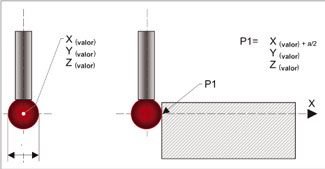
La estructura mecánica de una máquina de medición por coordenadas es, en la mayoría de casos, la representación física de un “Sistema de Referencia Cartesiana” en el que cada uno de los ejes representa uno de los ejes X,Y y Z del propio sistema de referencia. Cada eje se puede mover con relación a los otros y se centran en una regla de modo que en cualquier momento se pueda observar su posición respecto al origen del sistema de referencia. Si el origen es el mismo para los tres ejes y un punto se describe según su origen, la posición de este punto en el espacio(1) se puede saber en tiempo real según el valor de las tres coordenadas X, Y y Z indicadas por las reglas de los tres ejes de la máquina. Además, si el punto corresponde a un punto característico del sensor, por ejemplo, el centro de la bola del palpador, entonces se puede saber la posición del sensor en el espacio y se puede registrar en cualquier momento con la expresión X(valor), Y (valor) y Z (valor).
En un sensor táctil la punta está normalmente formada por una esfera de material duro con un nivel muy bajo de error. En las mediciones táctiles(2) la punta del sensor entra en contacto con la pieza que se tiene que medir para detectar la posición del punto que se ha tomado(3).
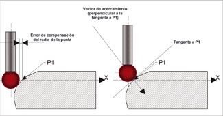
Si se conoce la posición en el espacio del centro de la punta así como su diámetro dinámico(4), entonces se pueden calcular las coordenadas de los puntos que se han tomado.
Para entender mejor el principio básico, el ejemplo que se muestra en la figura “1” representa la compensación en uno de los ejes de la pieza, esta compensación funciona en piezas designadas de “geometría simple” por su forma. En el caso de piezas de “geometría compleja”, la compensación se tendrá que hacer en el punto perpendicular y tangente al punto que se ha tomado, sin embargo, el principio de lectura es siempre el mismo.
La estructura mecánica de la CMM
- Dimensiones: derivan de la longitud de los ejes cartesianos, las dimensiones determinan el volumen de medición de la estructura. Las dimensiones pueden ir desde menos de medio metro hasta muchos metros, depende de los volúmenes de medición necesarios para el tipo de piezas que se tengan que medir, desde un motor hasta una carrocería.
Las dimensiones de la estructura mecánica tienen influencia determinante en las características de la CMM, como la “arquitectura” la “incertidumbre de medición” la reacción de la propia estructura a “gradientes térmicos”, etc.
- Arquitectura: las arquitecturas que puede tener una CMM se han ido consolidando a lo largo de los años. Depende de las dimensiones de la estructura mecánica y de lo que se quiera maximizar:
- El “dinamismo” (velocidad y aceleración de la CMM)
- Características metrológicas de la CMM
- Accesibilidad a la pieza que se tiene que medir
Las arquitecturas que se usan son las siguientes:
- Cantilever con mesa fija
- Puente móvil
- Gantry
- Puente en forma de “L”
- Puente fijo
- Cantilever con mesa móvil
- Columna
- Brazo móvil, brazo horizontal
- Mesa fija brazo horizontal
- Brazo articulado.
- Se entiende por espacio el volumen de medición de la CMM
- El más utilizado actualmente
- Con un palpador, cuando la punta entra en contacto con la pieza se genera un signo que permite capturar el valor de las tres coordenadas del centro de la punta en este preciso momento.
- Para obtener lecturas precisas el diámetro de la esfera de la punta se tiene que determinar usando la CMM con los mismos parámetros dinámicos que se utilizarán durante las actividades normales para calibrar.

