Optimization of the calculation of areas of venting: explosion protection
January 11, 2010
For many years, the most widely used method of explosion protection has been the of the venting of explosions. In its most simplified form, a panel of venting, consists of a thin metal sheet in the volume of the team. This panel provides the area enough pressure arising in case of explosion, relief and breaks at low pressure (typically 0.1 barg), releasing the pressure, the flames and combustion products, and therefore ensures that the equipment does not damage. In addition to providing the necessary relief area during an explosion, these elements of protection must comply with the Atex regulations of mandatory since June 2003.
While the calculation of areas of venting may seem relatively simple, other parameters of installation inherent to the team of venteado process should be taken into consideration. The use of the German standard VDI 3676 (2002) ' Pressure ventingt of dust explosions' and the European standard EN 14491 (2006) ' Dust explosion ventingt protective systems' are widely used.
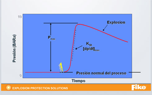
Example of the curve of a non vented explosion
The red line represents the atmospheric pressure inside a process equipment; Suppose 1 bara (0 barg). At any given time (lightning), begins a deflagration in the interior of the equipment caused by an ignition source. As a result of this source of ignition, starts a reaction of combustion generated an increase in pressure instantly to a Pmax value (for the majority of organic products Pmax varies between 5-10 bar). If it is not provided no relief system, the pressure reached Pmax, normally very higher than the pressure of design team, so the team will operate suffering severe damage and assuming a risk for people. The gradual decline since (not shown in the graph) to the atmospheric pressure Pmax occurs one time has been consumed the fuel mass.
The deflagration and detonation
A deflagration is a subsonic, typical phenomenon of explosions of dust, in which the pressure of an explosion wave traveling below the speed of sound (340 m/s) and where the flame front is followed with a speed between the 1-10 m/s. The typical reached maximum pressures for organic products rarely exceeds 10 bar.
Detonation is a supersonic phenomenon, in which the pressure wave and the flame of an explosion travelling ahead of the speed of sound. This is because there has been an understanding of the material prior to the explosion. Reached maximum pressure typical of detonations are greater than the achieved the deflagrate (of the order of 20-30 bar). That is why its consequences will be more catastrophic.
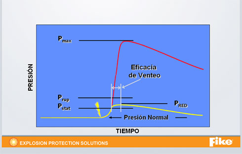
Example of the curve of a vented explosion
In this case the yellow line represents the atmospheric pressure inside a process equipment; Suppose 1 bara (0 barg). At any given time (lightning) starts a deflagration in the interior of the equipment caused by an ignition source. As a result of this ignition creates a combustion reaction, the pressure increases instantly, but in this case to reach the Pstat (panel opening pressure of venting) begins to liberate the explosion. However, the pressure continues to increase until a pressure known as Pred (reduced pressure or maximum relief pressure). This Pred must not exceed the Pes (design of the equipment or mechanical resistance pressure). Thus the pressure in the interior of the team will never Pmax values, by which the explosion not be avoided, but its effects can it be controlled.
Optimization of areas of venting product-burden
Annex A of the German standard VDI (Verein Deutscher Ingenieure) 3673 allows you to reduce and optimize areas of venting provided that the loading system of product of the venteado team to comply with certain conditions of transport. Research conducted on the different types of loading in silos, demonstrated that reduced pressures were lower than those who were with other conventional cargo systems (product through leveled grout injection). The reason for this was that this type of loads caused clouds of product within the team less turbulence and concentration, so that combustion rates were lower, as it was also the violence of the explosion.
Here are the formulas, as well as the range of application, for each type of product load:
Filling using pneumatic transportation with axial load of product
For containers with L ≤ 10 m height
To = X (1 + and · log (L / of)) in m2
For containers with L > 10 m height
To = 0. 1 L · X · (1 + And · log (L / of)) in m2
With
X = (1/Dz ·) (8.6 · log Pred max - 6) - 5.5 · (log Pred max + 3.7) · 0.011 Kst · DF
Y = 1.0715 Pred max -1.27
The equations are valid for:
-Higher axial downloading through a single pipe diameter Df without obstructions (are not considered instruments of measurement in pipe)
-Volume of the container between 53 m and 10,000 m3
-Speeds in pipe of cargo value ≤ 40 m/s
-Volumetric flow ≤ 2500 m3/h
-Diameter of the pipe of load ≤ 0.3 m
-Pstat ≤ 0.1 bar
-0.1 ≤ Pred ≤ 2 bar bar
-Pmax ≤ 9 bar
-50 bar · m / s ≤ Kst ≤ 300 bar · m / s
-Dz = ((4·))((V) / Π)1/3
Filling using pneumatic transportation with tangential load of product
To = X (1 + and ·log (L / of)) in m2
X = (1/Dz (8.6 / k · log (Pred max)-(Kst / 44) - 0.513) (- 5.5 / k) · log (Pred max) + Kst / 69 + 0.191) · 0.011 · KST · DF
Y = 0.166 · and (Kst / 129) · Max pred (- 1.27 / k)
With k = 1, for 0.1 ≤ bar Pred max ≤ 1 bar
With k = 2, for 1 ≤ bar Pred max ≤ 1.7 bar
The equations are valid for:
-Tangential discharge through a pipe of diameter DF ≤ 0.2 m
-Equipment/cylindrical silos without baffles or obstructions (measuring in pipe instruments are not considered)
-Volume of the container between3 to 6 m and 120 m3
-L / of (1 ≤ L / of ≤ 5)
-Speeds in pipe of cargo value ≤ 30 m/s
-Volumetric flow ≤ 2500 m3/h
-Pstat ≤ 0.1 bar
-0.1 ≤ Pred bar max ≤ 1.7 bar
-Pmax ≤ 9 bar
-100 bar · m / s ≤ Kst ≤ 220 bar · m / s
Filled by freefall product (rotary valves, helical screws)
Can use the equations used in 'Filling using pneumatic transportation with axial load of product' provided that the mass flow rate is limited to 8,000 kg/h.
Venting ducts I: internal explosions of venting
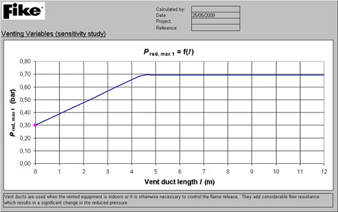
You can see that for different lengths of duct of venting made different low pressures, which implies an amendment of the pressure of design or mechanical resistance of the venteado team. In the design phase of a team can make changes to meet the needs of the venting, but there are certain teams in which such modifications are unworkable, either by cost or because they are already in operation. The recommendation to follow should they have to vent a team indoors is to be affixed, as close to a wall or roof of the installation team. This will prevent the introduction of the often uncomfortable ducts and therefore reduced pressures will be lower, so the mechanical strength of the equipment shall not be so high and it may reduce the cost of the equipment.
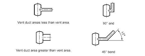
In Figure 1, shown below, you can see the designs of the ducts of venting permitted according to standards EN 14491:
-Through section to the panel of venting (exit vertical and/or horizontal).
-Through section to the panel of venting with inclination of 0 to 20 °.
-Through of venting with radius of curvature/diameter > 2 (gradual turn).

The designs of Figure 2, shown below, are not applied to the standard and should be avoided as far as possible. This is not to say that a 45º elbow is not a valid solution, what it means is that there has been enough evidence to ensure an efficient venting through application to EN 14491 formulas.
Venting internal explosions II: the Flash suppressor
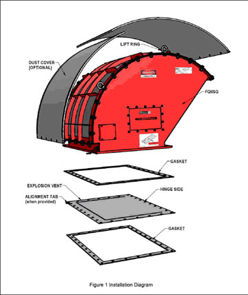
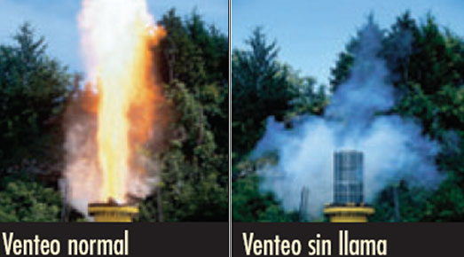
The Flash Hider are teams that somehow hinder the action of the venting free, given that they are a physical barrier to the release of the pressure and the flames. This fact causes the efficiency factor see decreased significantly. Each manufacturer limits the use of the the Flash suppressor to a determined Kst and Pred. The efficiency of these teams varies from 40% to 100% depending on the manufacturer and the volume of the equipment to protect. Generally the area of venting required the installation of units Flash Hider will be increased.
It is important to stress that the use of Flash suppressor is restricted to non-metallic organic products or indices of Kst < 300 bar · m/s. This is because the combustion heat generated by an explosion with metal products such as aluminum, magnesium, Silicon, iron, calcium, etc., is far superior to the which the Flash suppressor is able to absorb.
Considerations in the design of areas of venting
They have to make a number of considerations when designing areas of venting:
-It is important to select the type of panel suitable for the conditions of operation of the equipment. Take special attention to the gap in the system or cyclical and pulse pressure. All panels must accompany your Atex certificate issued by a notified body, as well as certificates of rupture.
-Check the efficiency of the panel of venting system or combined if the venting occurs with Flash suppressor units.
-It is recommended that the panels of venting incorporated indicators of rupture nailed plant controls to stop the process in case of explosion. This measure prevents feed fuel to the process and allows the closure of valves or other systems of dosing and pneumatic transport such as fans, blowers, rotary valves, bolts, elevators of bucket conveyors, redlers, etc.
-For the venting installations inside seek advice of specialists for the installation of ducts of venting or Flash suppressor units. The incorporation of these accompanying measures to the venting often necessary, have a great influence in the determination of the areas of venting.

